transformer outputs discussion cont'd...
@jacklee, I went to check out the LL1948 and the price took my breath away... until I realized I was looking at the silver-wire version. The copper-wire version is MUCH more reasonable.
I don't think that'd be a bad choice, but you'd never know until you try it and try some various strapping / R / C options. I do like the use of the Cardas wire, which I use in some of my builds when I can deal with the hassle of working with it.
I had also seen the units from @bisesik that @randytsuch mentioned and was going to mention them too. I will likely get a pair to try at some point, along with a pair of Sowters. AND I still have to try the LL1684 I have here too.
Also, @randytsuch, thanks for the info on Bud P. I had expected as much, having not seen him around the forums as much and getting no responses from Onetics. Pity, they are good and the price was stellar!
Greg in Mississippi
P.S. I should add I'm running the LL1544a transformers with the same 330R/34nF combo that I used on the Onetics. At some point I'll try Ian's recommended 510R/10nF, but i suspect I'll find that to be too little filtering.
Last edited:
clocks, clock power, and clock bypass Cs...
@jacklee, @wlowes, @Markw4, and @simon dart, thanks for your recent comments on various clocking options.
@jacklee, any more impressions you are willing to share on the Neutron Star 2 clock?
One takeaway I got from your report is that if one is using mostly one sampling family, there MAY be some benefit in only installing the clock needed for that family. I need to try that as almost all of my source material is ripped CDs.
Also interesting that using the Neutron Star 2 as you do does a separate power configuration similar to what @wlowes did with more typical clocks directly on the FiFoPi.
One thing to note it how the FiFoPi works with clock(s) enable pins.
- If you use only one clock, the enable pin is ignored. When using a single clock you don't need to use one with an enable pin, thought it works just as well if it has one.
- If you use two clocks, they BOTH must have enable pins. AND each must be of a different clock family (22 vs 24 or such). BUT they don't have to be of the same Fs... you can use a 22 and a 49 with no issues.
EVERYONE experimenting with various clock bypass Cs, what can you report so far?
Greg in Mississippi
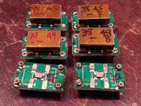
P.S. After some initial excitement with NDK SDAs, I'm back to Crysteks. I have assembled a few other options to try including a 22/24 Crystek pair and a pair of selected 90/98 NDK SA's I got from Acko a few years back. That doesn't mean I've given up on NDK SDAs... just that with the setups I'm running right now, I'm getting better results from the Crysteks.
I'm planning to wait and hear what others report on the clock bypass C front before jumping into that myself.
I also attached some pix of how I use remnants of the PC board from the adapters to space them as I cut (needed only for Crysteks on the original adapters) and solder the pins into the adapters. For the Crysteks on the original adapters, I first add the bypass Cs, then cut and solder the pins, and solder the clocks on last. On the newer adapters or any other clocks on the original ones, I do the C's first, then the clocks, and finally the pins.
@jacklee, @wlowes, @Markw4, and @simon dart, thanks for your recent comments on various clocking options.
@jacklee, any more impressions you are willing to share on the Neutron Star 2 clock?
One takeaway I got from your report is that if one is using mostly one sampling family, there MAY be some benefit in only installing the clock needed for that family. I need to try that as almost all of my source material is ripped CDs.
Also interesting that using the Neutron Star 2 as you do does a separate power configuration similar to what @wlowes did with more typical clocks directly on the FiFoPi.
One thing to note it how the FiFoPi works with clock(s) enable pins.
- If you use only one clock, the enable pin is ignored. When using a single clock you don't need to use one with an enable pin, thought it works just as well if it has one.
- If you use two clocks, they BOTH must have enable pins. AND each must be of a different clock family (22 vs 24 or such). BUT they don't have to be of the same Fs... you can use a 22 and a 49 with no issues.
EVERYONE experimenting with various clock bypass Cs, what can you report so far?
Greg in Mississippi
P.S. After some initial excitement with NDK SDAs, I'm back to Crysteks. I have assembled a few other options to try including a 22/24 Crystek pair and a pair of selected 90/98 NDK SA's I got from Acko a few years back. That doesn't mean I've given up on NDK SDAs... just that with the setups I'm running right now, I'm getting better results from the Crysteks.
I'm planning to wait and hear what others report on the clock bypass C front before jumping into that myself.
I also attached some pix of how I use remnants of the PC board from the adapters to space them as I cut (needed only for Crysteks on the original adapters) and solder the pins into the adapters. For the Crysteks on the original adapters, I first add the bypass Cs, then cut and solder the pins, and solder the clocks on last. On the newer adapters or any other clocks on the original ones, I do the C's first, then the clocks, and finally the pins.
Attachments
Last edited:
Some random responses, tips, and impressions...
This is stuff that doesn't neatly fit anywhere else...
1st, as someone else (@wlowes?) mentioned, I like how Ian has implemented LEDs to signal various operational and error status. BUT if you use his GB gear in a darkened room (like my downstairs bedroom setup), they can be VERY bright. I solve this by coloring them with a permanent magic marker (Sharpie brand here in the US). If you need them darker, use a paint-marker. See attached picture
2nd, when using Ian's ESS Controller adapter board on the non-isolated expansion connector of Ian's iFoPi, solder it so that the plug is slightly offset from center AWAY from the DAC board so that they don't interfere with each other.
3rd, also on Ian's ESS Controller, you can use the 10-pin FFC/FPC cable from Ian's regular GB items as shorter subs for the long cable supplied:
"18 10P 1.0mm FFC/FPC cables combo (3 cables) $3.95"
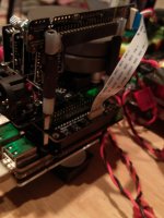
4th, if your setup is like mine that when you install Ian's ESS Controller on the non-isolated expansion connector of Ian's FiFoPi it is facing away from the listening postion, you can use some long screws, spacers, heatshrink and some appropriate plastic tubing (I used air hose tubing) to extend the controller above the DAC and output boards... see attached picture.
5th, if you go to order some spare fuses for Ians LiFePO4 supply, you might get confused as I did on whether to order the MRL or NRL version. They are the same fuse, so either works.
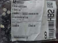
6th, I mentioned earlier in this thread or one of the other Ian threads that I'd list the specific supercap I intend to try... see attached picture. These are the ones recommended by Joe Rasmussen in his Alternative DAC filtering... thread a few years back. Note these are EOL and there are only 136 left at Mouser when I checked this morning.
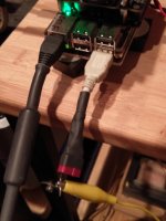
7th, in my setups I use a pair of fiber-media converters (FMCs) between the small network where I have the music source computer and the RPi player. That coupled with the isolation at the input of the FiFoPi means that there is no inherent ground connection for the RPi and FiFoPi input. In some cases this has caused a hum or buzz in my setups. To resolve, I cut the end off an old USB cable, seperate out the ground wire, and attach a clip-lead to it that I can attached to a convenient ground (in this case at the power supply I use for the RPi). See attached picture.
8th, some have discussed various schemes to control vibrations on the RPi->FiFoPi->DAC->output stage stack. I do this too with several techniques. First, the bottom portion of the stack is assembled with long brass screws (4-40 sized because that's the closest US equivalent) and brass spacers, tying it all together into a single coupled unit. More brass spacers fit on this stack, then I use shorter brass screws in the front and the longer brass-screw/spacer combo that holds the ESS Controller in the back.
Then I place the stack on compliant feet (I use some from Herbie's Audio) and place some weights on the stack (also Herbie's). The LiFePO4 supply is also on compliant feet (EAR here). All are on a bamboo board (where my standard AC supplies are mounted) and that is on compliant feed (also EAR) on a light rigid stand (Linn/Naim-ish).
I do this type of thing for all of my setups, RPi or otherwise, although the feet, weights, bases, and stands may be different depending on the application. See attached pictures.
Greg in Mississippi
This is stuff that doesn't neatly fit anywhere else...
1st, as someone else (@wlowes?) mentioned, I like how Ian has implemented LEDs to signal various operational and error status. BUT if you use his GB gear in a darkened room (like my downstairs bedroom setup), they can be VERY bright. I solve this by coloring them with a permanent magic marker (Sharpie brand here in the US). If you need them darker, use a paint-marker. See attached picture
2nd, when using Ian's ESS Controller adapter board on the non-isolated expansion connector of Ian's iFoPi, solder it so that the plug is slightly offset from center AWAY from the DAC board so that they don't interfere with each other.
3rd, also on Ian's ESS Controller, you can use the 10-pin FFC/FPC cable from Ian's regular GB items as shorter subs for the long cable supplied:
"18 10P 1.0mm FFC/FPC cables combo (3 cables) $3.95"
4th, if your setup is like mine that when you install Ian's ESS Controller on the non-isolated expansion connector of Ian's FiFoPi it is facing away from the listening postion, you can use some long screws, spacers, heatshrink and some appropriate plastic tubing (I used air hose tubing) to extend the controller above the DAC and output boards... see attached picture.
5th, if you go to order some spare fuses for Ians LiFePO4 supply, you might get confused as I did on whether to order the MRL or NRL version. They are the same fuse, so either works.
6th, I mentioned earlier in this thread or one of the other Ian threads that I'd list the specific supercap I intend to try... see attached picture. These are the ones recommended by Joe Rasmussen in his Alternative DAC filtering... thread a few years back. Note these are EOL and there are only 136 left at Mouser when I checked this morning.
7th, in my setups I use a pair of fiber-media converters (FMCs) between the small network where I have the music source computer and the RPi player. That coupled with the isolation at the input of the FiFoPi means that there is no inherent ground connection for the RPi and FiFoPi input. In some cases this has caused a hum or buzz in my setups. To resolve, I cut the end off an old USB cable, seperate out the ground wire, and attach a clip-lead to it that I can attached to a convenient ground (in this case at the power supply I use for the RPi). See attached picture.
8th, some have discussed various schemes to control vibrations on the RPi->FiFoPi->DAC->output stage stack. I do this too with several techniques. First, the bottom portion of the stack is assembled with long brass screws (4-40 sized because that's the closest US equivalent) and brass spacers, tying it all together into a single coupled unit. More brass spacers fit on this stack, then I use shorter brass screws in the front and the longer brass-screw/spacer combo that holds the ESS Controller in the back.
Then I place the stack on compliant feet (I use some from Herbie's Audio) and place some weights on the stack (also Herbie's). The LiFePO4 supply is also on compliant feet (EAR here). All are on a bamboo board (where my standard AC supplies are mounted) and that is on compliant feed (also EAR) on a light rigid stand (Linn/Naim-ish).
I do this type of thing for all of my setups, RPi or otherwise, although the feet, weights, bases, and stands may be different depending on the application. See attached pictures.
Greg in Mississippi
Attachments
-
 Feet (hard to see) small.jpg446.8 KB · Views: 362
 -
 Weights and Feet (hard to see) small.jpg579.2 KB · Views: 365
 -
 Grounding Connection small.jpg423.7 KB · Views: 352
 -
 Supercap small.jpg439.3 KB · Views: 359
 -
 Extended ESS Cntrllr w-short FPC-FFC cable small.jpg423.1 KB · Views: 661
 -
 Blackened LEDs small.jpg346.3 KB · Views: 677
Last edited:
So, I broke something, again 🙁
I took off the lcd board from the battery supply and mounted the cable the wrong way and removed it without powering off (yes I am a big moron for being this stuped 😡).
Now the screen is dead and the control knob does not work any more.
As I had another battery board lying around I took that lcd board to test but nothing happened.
Does this mean that the controller is broken? Is it fixable?
Last edited:
clocks, clock power & vibration dampening
Thanks for your update Greg.
I can recap where I am with these topics. I am in that happy place where the sound is at a level that I have more urge to listen than to solder 🙂 This usually means the obvious gremlins are gone and the sound is pretty engaging.
Everything has been running 7x24 for 3 weeks +, so likely pretty well burned in. Clock and FIFIOPi have a shared well filtered linear PS with 3 series regs with separate regs at the consumer.
I would like to experiment with super caps and would welcome advice. Can I place a super cap at the clock for example after the last regulator, or will I be triggering oscillation in the regulator? I realize a scheme like Ian's LifePO4 charger would be preferred, but it looks like there are reports of good experiences just with a supercap as a power reservoir at the consumer.
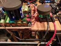
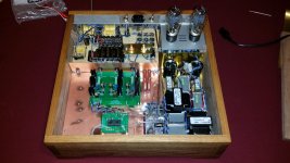
The other areas that I think deserves as much attention is vibration dampening and isolation. My basic chassis had some consideration for this topic from the beginning, and I think it is important with the FIFOPi as it was for other solutions. I built the chassis out of hardwood (American black walnut to be specific). The device along with my amps sit on stone (previously fireplace) which is on the cement foundation for the house which in turn is on piles to bedrock. So it is by chance already in a pretty anchored location. Inside the chassis I attempted to separate power supplies from sensitive consumers. So the PS for the tube output stage is in its own box lined with grounded brass or copper. The DAC section is in its own little world separated from PS or digital processors. The FIFO Pi is actually under the DAC mounted on a wood board attached to a metal plate separating the DAC section. (pic shows top half of chassis with 4 sections to separate PS's from DAC. Fifo below DAC) Its standoffs are mounted in silicon in holes in the wood. Then I pack sand bags in around the DAC, and on top of the whole cabinet. Even with the initial design for dampening, the addition of sand bags really cleans up the sound. There clearly is a smearing of the sound stage and a blurring of bass material that comes from feedback of the sound getting back to microphonic oscillators. (NDK SA) I have also had some success with simply covering the clocks with a blob of mac tac. I suspect potting them in silicon would work as well. I think there is a reasonable trade off in the physical architecture of the FIFOPi. The HAT approach is compact and eliminates one failure point, the ufl cable. On the other hand, it is a little harder to isolate the clock from vibration, so I chose to suspend the whole thing in silicon hanging from wood and then to shield the entire thing with sand. It would be difficult to suspend with floss, and you can't pot it as the RPi needs ventilation.
The next thing I am going to do is to shield the FIFO Pi from linear PS. The transformer and the PS for the dirty PS is in the same box as the FIFO PI. I have seen references suggesting that buying a super clock is wasted unless it is in its own chassis away from PS, so I'll add some brass plate around the FIFO to cut down on any stray electronic fields.
Thanks for your update Greg.
I can recap where I am with these topics. I am in that happy place where the sound is at a level that I have more urge to listen than to solder 🙂 This usually means the obvious gremlins are gone and the sound is pretty engaging.
Everything has been running 7x24 for 3 weeks +, so likely pretty well burned in. Clock and FIFIOPi have a shared well filtered linear PS with 3 series regs with separate regs at the consumer.
I would like to experiment with super caps and would welcome advice. Can I place a super cap at the clock for example after the last regulator, or will I be triggering oscillation in the regulator? I realize a scheme like Ian's LifePO4 charger would be preferred, but it looks like there are reports of good experiences just with a supercap as a power reservoir at the consumer.
The other areas that I think deserves as much attention is vibration dampening and isolation. My basic chassis had some consideration for this topic from the beginning, and I think it is important with the FIFOPi as it was for other solutions. I built the chassis out of hardwood (American black walnut to be specific). The device along with my amps sit on stone (previously fireplace) which is on the cement foundation for the house which in turn is on piles to bedrock. So it is by chance already in a pretty anchored location. Inside the chassis I attempted to separate power supplies from sensitive consumers. So the PS for the tube output stage is in its own box lined with grounded brass or copper. The DAC section is in its own little world separated from PS or digital processors. The FIFO Pi is actually under the DAC mounted on a wood board attached to a metal plate separating the DAC section. (pic shows top half of chassis with 4 sections to separate PS's from DAC. Fifo below DAC) Its standoffs are mounted in silicon in holes in the wood. Then I pack sand bags in around the DAC, and on top of the whole cabinet. Even with the initial design for dampening, the addition of sand bags really cleans up the sound. There clearly is a smearing of the sound stage and a blurring of bass material that comes from feedback of the sound getting back to microphonic oscillators. (NDK SA) I have also had some success with simply covering the clocks with a blob of mac tac. I suspect potting them in silicon would work as well. I think there is a reasonable trade off in the physical architecture of the FIFOPi. The HAT approach is compact and eliminates one failure point, the ufl cable. On the other hand, it is a little harder to isolate the clock from vibration, so I chose to suspend the whole thing in silicon hanging from wood and then to shield the entire thing with sand. It would be difficult to suspend with floss, and you can't pot it as the RPi needs ventilation.
The next thing I am going to do is to shield the FIFO Pi from linear PS. The transformer and the PS for the dirty PS is in the same box as the FIFO PI. I have seen references suggesting that buying a super clock is wasted unless it is in its own chassis away from PS, so I'll add some brass plate around the FIFO to cut down on any stray electronic fields.
Attachments
Some thoughts on opamps & regulators/power supplies
@redjr and @Markw4, interesting comments on opamps in Ian's IVStd I/V stage board.
@redjr, looking again at the manual, the OPA1622 is only recommended as an upgrade for U3, not all of the positions. Ian does recommend the OPA1612 for U1 and U2. I've not tried these yet, but have them all here along with OPA1642 and OPA1662 to try. I HAVE tried both the LKS and Sparkos discrete opamps in positions U1 & U2 and found them significant upgrades over the included opamps. I don't have a read on the sonics yet as I've been trying several power and I/V filtering options.
@Markw4, comparing the schematics of your output stage from your developmental ES9038Q2M DAC boards and Ian's IVStd, I see that Ian using a much smaller filter capacitor in the 1st (I/V) stage. If I understand it correctly, that would mean Ian's IVStd is handling a much wider bandwidth than your output stage's IV stage. Could that be contributing to the increased operating temperature you've experienced running the OPA1612 in Ian's IVStd?
Also, @Markw4 & @TioFrancotirador, thanks for your comments on various regulator and power schemes. A couple of comments... first, @Markw4, I understood the TP Trident SRs used the ADM7155 (fixed) or ADM7154 (variable) regulators, not the ADM7150 (fixed) or ADM7151 (variable) regulators. See post #84 of this thread:
https://www.diyaudio.com/forums/twi...nt-evolves-version-3-a.html?highlight=adm7151
Has that changed? AFAIK, that's why TP recommends a maximum of 5V for those regulator boards. The datasheet for the ADM7154/7155 suggest slightly lower noise, but except for the much lower maximum Vin of 5.5V versus 16V for the ADM7150/7151, they seem very similar.
Also @Markw4, thanks for the reminder on the trick of pre-loading regulators to better their performance. I first heard of that and used it back in the 80s and 90s, though it fell out of my toolbox over the years. Good to have it back! Have you had the chance yet to try pre-loading the ADM715x or LT304x regulators yet to see if that has them perform better in your assessments?
Interesting to hear your results with the Dexa UWB2. I used the original UWB in a number of applications over the years and the new UWB2 in only one application so far, but it performed very well there. I expect the UWB2 is better, but have not compared them directly.
@TioFrancotirador, I'd add to your list the Sparkos regulators and the 3-parallel and 6-parallel LT3045 regulator boards from MPAudio, both of which have powered my Katana to very good effect, with the 6-parallel besting the 3-parallel. Both of these also bested a pair of 5V Reflektors powering the Katana, though I hear the new UltraBiB is a different animal. Also, the New Class D UWB listed on the Belleson website is AFAIK the older one, not the UWB2 that Markw4 recently used.
Finally, I've been trying different power supply schemes on my Ian GB setups. From worse to best, my results are:
- Anything that powers the FiFoPi with 3.3V into the on-board LDOs. No combination configured this way sounded very good to me.
- Powering the FiFoPi with a 5V 3-parallel MPAudio regulator and the DAC board with a 3.3V 4-parallel OPc LT3042 board, both fed from my standard AC raw DC supplies (See an early post in the 'Getting the Best out of Allo's Katana...' thread for details on those supplies).
- Powering the FiFoPi through it's LDOs from a 5v-charged UCPi being constantly charged from an Uptone Audio LPS-1.2 and the DAC board with one of the 3.3V rails from Ian's LiFePO4 supply.
- Bypassing the LDOs in the FiFoPi and feeding it and the DAC board each from a 3.3V rail from Ian's LiFePO4. This was a significant step above the previous level.
- Substituting a 3.3V UCPi, again being constantly charged from an LPS-1.2 for the 3.3V battery rail on the FiFoPi. Yup @TioFrancotirador, my experience is like yours that a good Ultracap setup will best a good battery setup. I'm eagerly awaiting Ian's full UC supply, though I expect it to be more expensive than his LiFePO4 supply. AND at some point I'll try 2 3.3V UCPi's.
The performance level using Ian's LiFePO4 supply direct into the FiFoPi, DAC board, and active output stage bypassing any regulators is very good and getting to the same level as my other best setups here. IF you are using Ian's LiFePO4 supply and haven't bypassed the FiFoPi LDOs yet, you really need to do that, you will be happy with the results.
Greg in Mississippi
P.S. @Markw4, what regulators were compared in the Linear Audio article you mentioned on your DAC board thread? That'll help me justify buying it.
THANKS!
Last edited:
...
@redjr, looking again at the manual, the OPA1622 is only recommended as an upgrade for U3, not all of the positions. Ian does recommend the OPA1612 for U1 and U2. I've not tried these yet, but have them all here along with OPA1642 and OPA1662 to try. I HAVE tried both the LKS and Sparkos discrete opamps in positions U1 & U2 and found them significant upgrades over the included opamps. I don't have a read on the sonics yet as I've been trying several power and I/V filtering options.
Thanks for calling that to my attention. I must have misread the docs. Anyway, I plan on swapping in OPA1612 for U1 and U2 when my brown dog adapters arrive.
@redjr and @Markw4, interesting comments on opamps in Ian's IVStd I/V stage board.
@Markw4, comparing the schematics of your output stage from your developmental ES9038Q2M DAC boards and Ian's IVStd, I see that Ian using a much smaller filter capacitor in the 1st (I/V) stage. If I understand it correctly, that would mean Ian's IVStd is handling a much wider bandwidth than your output stage's IV stage. Could that be contributing to the increased operating temperature you've experienced running the OPA1612 in Ian's IVStd?
I haven't specifically tested that idea. Anyone is welcome to experiment though. Seems more likely to me that my second modded dac turned out differently in that respect mostly due to layout. Haven't proven it though.
Also, @Markw4 & @TioFrancotirador, thanks for your comments on various regulator and power schemes. A couple of comments... first, @Markw4, I understood the TP Trident SRs used the ADM7155 (fixed) or ADM7154 (variable) regulators, not the ADM7150 (fixed) or ADM7151 (variable) regulators. See post #84...
I have a recent issue 3.3v Trident-SR right here. Marking on the IC is "715033". I would guess manufacturing changes might have occurred at some point along the way. Probably doesn't much matter, though. As you say, the parts are all pretty similar.
Also @Markw4, thanks for the reminder on the trick of pre-loading regulators to better their performance. I first heard of that and used it back in the 80s and 90s, though it fell out of my toolbox over the years. Good to have it back! Have you had the chance yet to try pre-loading the ADM715x or LT304x regulators yet to see if that has them perform better in your assessments?
Not yet. I am kind of hoping others will want to get more involved in doing research to help everyone else. I have plenty on my plate already trying to keep things moving along in the ES9038Q2m board thread.
Interesting to hear your results with the Dexa UWB2. I used the original UWB in a number of applications over the years and the new UWB2 in only one application so far, but it performed very well there. I expect the UWB2 is better, but have not compared them directly.
I don't want to go into all the reasons here, but I think there are some good reasons to try UWB2 over some of the other highly ranked alternatives at this time. Also likely worth a try are Nazar regulators (which are diy only, some useful posts on that from eziitis available in ES9038Q2M board thread).
@Markw4, what regulators were compared in the Linear Audio article you mentioned on your DAC board thread? That'll help me justify buying it.
The article is at: Linear Audio | your tech audio resource
For some free related info, look for the text: "Color graphs for Jack Walton's regulator article in Vol 4" on the following page:
Downloads | Linear Audio
Last edited:
@Greg,
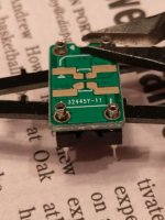
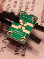
The LL1948 looks good on paper but is more money, plus it's only 1:1 instead of 1:4 so I'm still on the fence. The units from @bisesik is also very promising and is specifically designed for current-output DACs so I went ahead ordered a pair.
One thing of note in reading @bisesik's thread is that in his schematic the loading resistor is in the transformer secondary instead of the primary as in Ian's board. I asked @bisesik about this and he indicated both works and one has to experiment. Theoretically if the loading resistor is in the secondary then it means all output currents from the DAC run pass the transformer, which seems like a good thing. This could be an interesting thing to try, even in Ian's board.
On R/C I have not installed the C and haven't find any issue. Perhaps because I use a passive AVC as the preamp (Bentaudio AVC-1) so some filtering is already in place.
I also just swapped the R to an AudioNote one but the sound is harder. I hope its due to lack of break-in (as the AudioNote R is $$$). Otherwise I'll need to swap the Dale R back.
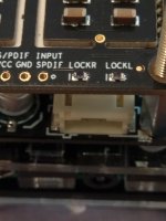
On the clocks, I haven't got a chance to do more evaluations yet. My experiences so far is that tying the grounds of the NS2 board to the fifopi board is definitely bad. The NS2 output is unique in that it is transformer-coupled so the whole thing is galvanic-isolated. The same cannot be achieved by powering normal clocks even using a separate power unless one add such transformer coupling which would not be easy.
On the enable pin: the fifopi can work even if the clock does not implement enable but whether that will sound good is a question. The NS2 supports it but to make it work one has to tie the grounds which is bad so I came up with an idea of using an optocoupler to implement it without the ground connection. I talked to Lars of NewClassD about this and he went ahead and implemented it and confirmed that it works. I'm now ordering the parts and will implement that too and if all went well then I can install both clocks using NS2 clocks.
Finally, I echo your recommendation on bypassing the onboard LDO in the fifopi. It makes a big difference and is a must (just two solder joints).
The LL1948 looks good on paper but is more money, plus it's only 1:1 instead of 1:4 so I'm still on the fence. The units from @bisesik is also very promising and is specifically designed for current-output DACs so I went ahead ordered a pair.
One thing of note in reading @bisesik's thread is that in his schematic the loading resistor is in the transformer secondary instead of the primary as in Ian's board. I asked @bisesik about this and he indicated both works and one has to experiment. Theoretically if the loading resistor is in the secondary then it means all output currents from the DAC run pass the transformer, which seems like a good thing. This could be an interesting thing to try, even in Ian's board.
On R/C I have not installed the C and haven't find any issue. Perhaps because I use a passive AVC as the preamp (Bentaudio AVC-1) so some filtering is already in place.
I also just swapped the R to an AudioNote one but the sound is harder. I hope its due to lack of break-in (as the AudioNote R is $$$). Otherwise I'll need to swap the Dale R back.
On the clocks, I haven't got a chance to do more evaluations yet. My experiences so far is that tying the grounds of the NS2 board to the fifopi board is definitely bad. The NS2 output is unique in that it is transformer-coupled so the whole thing is galvanic-isolated. The same cannot be achieved by powering normal clocks even using a separate power unless one add such transformer coupling which would not be easy.
On the enable pin: the fifopi can work even if the clock does not implement enable but whether that will sound good is a question. The NS2 supports it but to make it work one has to tie the grounds which is bad so I came up with an idea of using an optocoupler to implement it without the ground connection. I talked to Lars of NewClassD about this and he went ahead and implemented it and confirmed that it works. I'm now ordering the parts and will implement that too and if all went well then I can install both clocks using NS2 clocks.
Finally, I echo your recommendation on bypassing the onboard LDO in the fifopi. It makes a big difference and is a must (just two solder joints).
@Greg,
The LL1948 looks good on paper but is more money, plus it's only 1:1 instead of 1:4 so I'm still on the fence. The units from @bisesik is also very promising and is specifically designed for current-output DACs so I went ahead ordered a pair.
One thing of note in reading @bisesik's thread is that in his schematic the loading resistor is in the transformer secondary instead of the primary as in Ian's board. I asked @bisesik about this and he indicated both works and one has to experiment. Theoretically if the loading resistor is in the secondary then it means all output currents from the DAC run pass the transformer, which seems like a good thing. This could be an interesting thing to try, even in Ian's board.
On R/C I have not installed the C and haven't find any issue. Perhaps because I use a passive AVC as the preamp (Bentaudio AVC-1) so some filtering is already in place.
I also just swapped the R to an AudioNote one but the sound is harder. I hope its due to lack of break-in (as the AudioNote R is $$$). Otherwise I'll need to swap the Dale R back.
On the clocks, I haven't got a chance to do more evaluations yet. My experiences so far is that tying the grounds of the NS2 board to the fifopi board is definitely bad. The NS2 output is unique in that it is transformer-coupled so the whole thing is galvanic-isolated. The same cannot be achieved by powering normal clocks even using a separate power unless one add such transformer coupling which would not be easy.
On the enable pin: the fifopi can work even if the clock does not implement enable but whether that will sound good is a question. The NS2 supports it but to make it work one has to tie the grounds which is bad so I came up with an idea of using an optocoupler to implement it without the ground connection. I talked to Lars of NewClassD about this and he went ahead and implemented it and confirmed that it works. I'm now ordering the parts and will implement that too and if all went well then I can install both clocks using NS2 clocks.
Finally, I echo your recommendation on bypassing the onboard LDO in the fifopi. It makes a big difference and is a must (just two solder joints).
As for the R. I found Vishay VAR Z-foil (naked foil) in audio signal path to be the best. Their specs are incredible. You can try them instead audio note.
@Greg Stewart
Thank you for sharing your insights!
I chcked regulators you recommend. However once you try audio nirvana with ultracaps it is hard to find any motivation to dig deeper regulators topic 🙂
Do not know about @ians plans in regard of ultracap PSU. I just wish he made it modular way. Meaning each ultra cap reg would be of form factor of regular PSU. So that everyone would easily replace his exsiting diyinhk, salas, whatever PSU. You would simply connect it to AC or (DC19-24V) and set the voltage range. That is it!. You would also get only as many you need. E.g.: In my case I do not need +/-15V, because i prefer output transformers. I would only need one (3.15-3.45V) to power AVCC, and another (4.75-5.25V) to power local regs of all digital isolated rest like fifoPi and DVCC. For the RPI I would just use low noise 5V linear PSU. At the least this is my todays dream setup and this were my audio experience led me to.
EVERYONE experimenting with various clock bypass Cs, what can you report so far?
Greg in Mississippi
I soldered my NDK SDA's straight onto the FiFoPi directly. I didn't use adaptors so my tinkering was limited to adding extra supply decoupling caps bridged over the top. I tried 10nF, 100nF and 10uF all with leads formed as tight as I could and soldered to the adjacent larger footprint pads. In all cases they degraded the sound (10nF catastrophically so) and this could also be seen in the DPLL ratio on the controller.
Please correct me if I'm wrong Ian, but there appears to be decoupling to the clock power on the underside of the PCB and in my case adding to it didn't result in any improvements.
I guess the adaptor traces and connectors add enough inductance to disassociate the extra capacitance on the adaptor boards enough not to cause trouble.
As I said at RF everything electrical and physical becomes significant, so different setups will behave ....differently!
@Greg Stewart
As far As salas regs, then yes:
Ref - D is only good with jfet mod and good quality cap on led filtering. I found mundorf 4-pin to work best here.
Bib 1.3 oh yes, this is beast! Z-out ~150uOhm!!! Noise far below 2nV/HZ1/2. When I use it with ak4497 I could not tell the difference whether it is ultracap or BiB.
(connected to AVCC). Pity it cannot work as low as 3.3V so I would try it on es9038q2m.
As for the R. I found Vishay VAR Z-foil (naked foil) in audio signal path to be the best. Their specs are incredible. You can try them instead audio note.
Ahhh yes! I should have thought of that when I ordered from pcx two weeks ago. Will have to wait for the next batch then.
I just listened a bit and found that the AudioNote R does mellow out and is now very rich in harmonic. Whew!
I learned that monitoring the DPLL ratio through the controller is a powerful tool to tell you if you are on the right or wrong track.
Hi Simon,
Could you elaborate a bit on how to use the DPLL ratio to monitor the signal/clock quality? I use the true-sync mode with DPLL bandwidth = 0 and couldn't seem to activate the DPLL monitor.
Thanks.
If you're in the US, I'd get the Texas Components "nude" resistors, the OEM for them
texas components audio resistors
Sowter's example circuit also shows a resistor on the secondary
DAC I/V CONVERSION OUTPUT TRANSFORMERS
texas components audio resistors
Sowter's example circuit also shows a resistor on the secondary
DAC I/V CONVERSION OUTPUT TRANSFORMERS
Hi Simon,
Could you elaborate a bit on how to use the DPLL ratio to monitor the signal/clock quality? I use the true-sync mode with DPLL bandwidth = 0 and couldn't seem to activate the DPLL monitor.
Thanks.
As Ian mentions in the manual you do have to turn true SYNC off to see the DPLL ratio, with true SYNC enabled it turns off the DPLL and the ratio displayed is meaningless.
I set the DPLL Bandwidth to 1 (Lowest) with true SYNC off for testing, lower numbers indicate better clock quality as the DPLL is doing less work.
@randytsuch,
Thanks for the link. I'm not in the US so will have to batch items to purchase to save on shipping.
The Sowter looks good too. Have anyone tried it?
@simon,
Thanks for the explanation. Let me try that later.
Thanks for the link. I'm not in the US so will have to batch items to purchase to save on shipping.
The Sowter looks good too. Have anyone tried it?
@simon,
Thanks for the explanation. Let me try that later.
I couldn't find much information on the sowter iv's when I searched, lundahls seem to be more popular for this application.
Here is a thread on 1684's for iv
Super V/i converted (LL1684 )
Circuit designed by Andrea, and the interesting thing about it is the 10k on the primary, which would put the dac in voltage out mode.
Here is a thread on 1684's for iv
Super V/i converted (LL1684 )
Circuit designed by Andrea, and the interesting thing about it is the 10k on the primary, which would put the dac in voltage out mode.
I couldn't find much information on the sowter iv's when I searched, lundahls seem to be more popular for this application.
Here is a thread on 1684's for iv
Super V/i converted (LL1684 )
Circuit designed by Andrea, and the interesting thing about it is the 10k on the primary, which would put the dac in voltage out mode.
I have this circuit as well. It is for voltage output dacs. It is very good. I used it with akms and ess. SQ depands on the quality of cap used. I used Jantzen Alumen 10uf, but one could use lower value and even better quailty e.g.: 2.2uf Mundorf Supreme EVO Oil Silver Gold. Eventually Super V/I has been replaced with Teramoto Finemet, which so far are the best for me!
Last edited:
- Home
- Source & Line
- PC Based
- IanCanada's Latest RPi GB Goodies Impressions... and your tweaks, mods and hints...