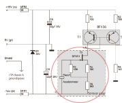
I see a fuse holder but I don’t see a power entry or switch. Are they on the top?
Very neat little box / setup.
Very neat little box / setup.
I see a fuse holder but I don’t see a power entry or switch. Are they on the top?
Very observant! I need to get a suitable strain relief for power cord entry. I wasn't going to bother with a power switch. It will switch on with the rest of the equipment. It will generate a transient, but it should die out before the power amp relay engages. If not, well... 🙂
rschamp regarding your TINA simulation. Can you share the *.CIR file with me?
I want to do simulation as well with current feedback and dipole woofers.
Thanks 🙂
Hmmm. I tried exporting a .CIR file and I get an error that spice models are missing for the switches. I could try removing them first but you would have to put them back.
Ok to remove parts.. Thanks for good work!
I'll give that a try. I'm suspicious I might keep getting these error messages. If so, can you use the schematic file? I posted it earlier.
Hmmm. I tried exporting a .CIR file and I get an error that spice models are missing for the switches. I could try removing them first but you would have to put them back.
esl 63:
Good news - I was able to save the .CIR file after deleting the switches. See attached.
Bad news - I had a LOT of single and double-throw switches in the circuit for experimentation that I had to delete - I hope you can figure out where they were!
Attachments
@ rscamp, nice tidy looking setup 🙂
Before diving into the details, it is probably a good idea go over some basics to ensure we are all talking the same language. Different branches of engineering use different terms for things, so best to describe how they will be used here to avoid confusion. Otherwise, a few internet searches may have you scratching your head more than necessary.
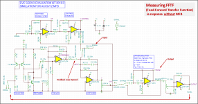
Attachment #1: Feed-Forward Transfer Function (FFTF)
This is the woofer SPL response measured when the input signal is applied to the mixer input but the feedback loop has been opened somewhere. It can also be described as the response without MFB. Frequently it is mistakenly called the open-loop response.
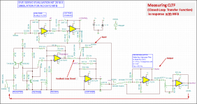
Attachment #2: Closed-Loop Transfer Function (CLTF)
This is the woofer SPL response measured when the input signal is applied to the mixer input and the feedback loop is closed and active. It can also be described as the response with MFB.
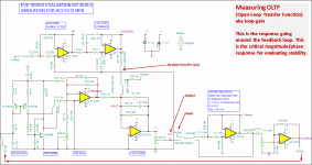
Attachment #3: Open-Loop Transfer Function (OLTF)
This is the response measured around the feedback loop. To measure, you must open the loop somewhere(hence the name) and inject the input signal while monitoring the response after the signal has traversed the loop and come back to the break where you are injecting the signal. Amplifier designers usually call this loop-gain. This is the measurement that is needed to evaluate the stability of the MFB system as well the distortion reduction potential. If you would rather not break into MFB electronics to perform this measurement, you can calculate the OLTF from measurements of the FFTF and CLTF taken with the microphone in the same position. REW and most other measurement systems can perform this simple math.
OLTF = (FFTF – CLTF) / CLTF
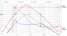
Attachment #4: Phase margin is determined from the OLTF by finding the 0db crossing points; the frequencies for which gain has fallen to 1. Trace up/down to see what the phase is at these frequencies and compare it to +/-180 degrees. Remember if phase shifts by 180 degrees in the feedback loop you have created an oscillator. So, phase margin is a measure of how close the MFB circuit is to breaking into oscillation. I usually shoot for phase margin of 60deg which is nice and stable, showing only minor peaking which is easily EQ’d in the pre-amp section. If you aim for 90deg phase margin or better to avoid any peaking you will wind up with so little OLTF gain that you won’t be getting much distortion reduction. As with most engineering endeavors, compromises abound.
Before diving into the details, it is probably a good idea go over some basics to ensure we are all talking the same language. Different branches of engineering use different terms for things, so best to describe how they will be used here to avoid confusion. Otherwise, a few internet searches may have you scratching your head more than necessary.
Attachment #1: Feed-Forward Transfer Function (FFTF)
This is the woofer SPL response measured when the input signal is applied to the mixer input but the feedback loop has been opened somewhere. It can also be described as the response without MFB. Frequently it is mistakenly called the open-loop response.
Attachment #2: Closed-Loop Transfer Function (CLTF)
This is the woofer SPL response measured when the input signal is applied to the mixer input and the feedback loop is closed and active. It can also be described as the response with MFB.
Attachment #3: Open-Loop Transfer Function (OLTF)
This is the response measured around the feedback loop. To measure, you must open the loop somewhere(hence the name) and inject the input signal while monitoring the response after the signal has traversed the loop and come back to the break where you are injecting the signal. Amplifier designers usually call this loop-gain. This is the measurement that is needed to evaluate the stability of the MFB system as well the distortion reduction potential. If you would rather not break into MFB electronics to perform this measurement, you can calculate the OLTF from measurements of the FFTF and CLTF taken with the microphone in the same position. REW and most other measurement systems can perform this simple math.
OLTF = (FFTF – CLTF) / CLTF
Attachment #4: Phase margin is determined from the OLTF by finding the 0db crossing points; the frequencies for which gain has fallen to 1. Trace up/down to see what the phase is at these frequencies and compare it to +/-180 degrees. Remember if phase shifts by 180 degrees in the feedback loop you have created an oscillator. So, phase margin is a measure of how close the MFB circuit is to breaking into oscillation. I usually shoot for phase margin of 60deg which is nice and stable, showing only minor peaking which is easily EQ’d in the pre-amp section. If you aim for 90deg phase margin or better to avoid any peaking you will wind up with so little OLTF gain that you won’t be getting much distortion reduction. As with most engineering endeavors, compromises abound.
Attachments
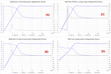
Next, let’s take a quick look at woofer response(phase in particular) and why it is problematic for wrapping a feedback loop around. Then, describe some of the tools(ie filters) available to deal with the phase problems. Finally describe what the difference is between putting filters in the feed-forward path(between mixer and woofer) or in the feed-back path (between accelerometer and mixer).
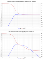
Attachment #1: Ideally, a woofer operating in free air or in a sealed enclosure will have a 2nd order HP filter response. The response would be flat above resonance, transitioning to a -12dB/oct slope below resonance. Phase shifts from 0deg to +180deg. Wrapping a feedback loop around this would be problematic. Still sticking with the ideal case, if we inserted a filter that shifted all phase by -90deg then we would have a loop that only varied +/-90deg and it would be nice and stable. But, back in the real world, woofers have inductance which adds an additional -45deg to -90deg of phase lag above resonance. Suddenly the easy fix of a -90deg phase adjustment doesn’t look quite so easy.
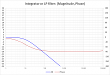
Attachment #2: The filter circuit that shifts phase by -90deg at all frequencies is called an integrator. But, it requires infinite gain at DC. In the real world, a LP filter is used instead…often called a leaky integrator. Above the turn-over point, the phase asymptotically approaches the desired -90deg shift. In the EVE circuit, C9 and R18 define the turn-over point for a LP filter built around IC1B.
Commercial motional feedback woofer available sort of
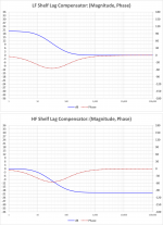
Attachment #3: Lag Compensation filters can also be used to provide targeted phase adjustment where it is needed (ie close to the 0dB crossing frequency) without unnecessarily impacting higher frequency phase margins. In the EVE circuit, C10 and R17/R18 define a lag compensation filter around IC1B. Notice that C6 and R14/R11/5Ktrimmer also define a lag compensation filter around IC1A in the form of a LF shelf circuit. The manual describes C6 as being used for a sensor LP filter, but with IC1A configured as a non-inverting amplifier gain will never fall below 1. The board does provide a LP filter for the sensor using C1 and R2, which currently is set to roll off above 40kHz. You won’t see this in your TINA-TI circuit which is feeding the input from a low impedance voltage source. The actual sensor will act more like a voltage controlled current source. I’ll see if I can figure out how to do that with TINA-TI.
Attachment #4: Lead Compensation filters are advantageous for improving phase margins at the HF end of the bandwidth. The EVE board does not include any, but this is not an issue since they aren’t really needed for the target bandwidth of a subwoofer.
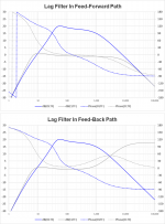
OK, so we have measured the OLTF and decided on a filter to use to improve the LF phase margin. Where do we put the filter? In the feed-back path? In the feed-forward path? Does it matter? In general, all phase adjustment filters should be put in the feed-ward path. The reason is that in addition to adjusting phase, you can see that the filters have the undesired consequence of changing the magnitude from flat. By putting the filter in the feed-forward path, you take advantage of the fact that the feedback loop will flatten the response not only of the woofer, but also the filter. If the filter is placed in the feed-back path, the stability of the feedback loop will be the same as if it had been placed in the feed-forward path. The difference is that the response of the filter will not be flattened. In fact, the mixer will see the filter response as an error signal and try to compensate for it…effectively resulting in a mirror image of the filter magnitude showing up in the CLTF. So, the only filters that are advantageous to have in the feed-back path are those to compensate for short-comings of the accelerometer.
Attachment #5: Here is an example of a woofer with a Lag Compensation filter put either in the feed-forward path, or feed-back path. Note that the OLTF looks essentially identical. But, the feed-forward location results in a flat CLTF while the feed-back location results in a rising resopnse(ie mirror image of the compensation filter). Often a frequency response rise like this when a filter is added in the feedback loop is incorrectly understood to mean that the phase margin has been reduced. Remember, the stability of the feedback loop is shown in the OLTF phase margin not in the CLTF response.
Let me know if you have any questions so far.
I think the next step will be to pull in some real measured data and show trends of the OLTF and CLTF as the different EVE filters are adjusted.
Attachment #1: Ideally, a woofer operating in free air or in a sealed enclosure will have a 2nd order HP filter response. The response would be flat above resonance, transitioning to a -12dB/oct slope below resonance. Phase shifts from 0deg to +180deg. Wrapping a feedback loop around this would be problematic. Still sticking with the ideal case, if we inserted a filter that shifted all phase by -90deg then we would have a loop that only varied +/-90deg and it would be nice and stable. But, back in the real world, woofers have inductance which adds an additional -45deg to -90deg of phase lag above resonance. Suddenly the easy fix of a -90deg phase adjustment doesn’t look quite so easy.
Attachment #2: The filter circuit that shifts phase by -90deg at all frequencies is called an integrator. But, it requires infinite gain at DC. In the real world, a LP filter is used instead…often called a leaky integrator. Above the turn-over point, the phase asymptotically approaches the desired -90deg shift. In the EVE circuit, C9 and R18 define the turn-over point for a LP filter built around IC1B.
Commercial motional feedback woofer available sort of
Attachment #3: Lag Compensation filters can also be used to provide targeted phase adjustment where it is needed (ie close to the 0dB crossing frequency) without unnecessarily impacting higher frequency phase margins. In the EVE circuit, C10 and R17/R18 define a lag compensation filter around IC1B. Notice that C6 and R14/R11/5Ktrimmer also define a lag compensation filter around IC1A in the form of a LF shelf circuit. The manual describes C6 as being used for a sensor LP filter, but with IC1A configured as a non-inverting amplifier gain will never fall below 1. The board does provide a LP filter for the sensor using C1 and R2, which currently is set to roll off above 40kHz. You won’t see this in your TINA-TI circuit which is feeding the input from a low impedance voltage source. The actual sensor will act more like a voltage controlled current source. I’ll see if I can figure out how to do that with TINA-TI.
Attachment #4: Lead Compensation filters are advantageous for improving phase margins at the HF end of the bandwidth. The EVE board does not include any, but this is not an issue since they aren’t really needed for the target bandwidth of a subwoofer.
OK, so we have measured the OLTF and decided on a filter to use to improve the LF phase margin. Where do we put the filter? In the feed-back path? In the feed-forward path? Does it matter? In general, all phase adjustment filters should be put in the feed-ward path. The reason is that in addition to adjusting phase, you can see that the filters have the undesired consequence of changing the magnitude from flat. By putting the filter in the feed-forward path, you take advantage of the fact that the feedback loop will flatten the response not only of the woofer, but also the filter. If the filter is placed in the feed-back path, the stability of the feedback loop will be the same as if it had been placed in the feed-forward path. The difference is that the response of the filter will not be flattened. In fact, the mixer will see the filter response as an error signal and try to compensate for it…effectively resulting in a mirror image of the filter magnitude showing up in the CLTF. So, the only filters that are advantageous to have in the feed-back path are those to compensate for short-comings of the accelerometer.
Attachment #5: Here is an example of a woofer with a Lag Compensation filter put either in the feed-forward path, or feed-back path. Note that the OLTF looks essentially identical. But, the feed-forward location results in a flat CLTF while the feed-back location results in a rising resopnse(ie mirror image of the compensation filter). Often a frequency response rise like this when a filter is added in the feedback loop is incorrectly understood to mean that the phase margin has been reduced. Remember, the stability of the feedback loop is shown in the OLTF phase margin not in the CLTF response.
Let me know if you have any questions so far.
I think the next step will be to pull in some real measured data and show trends of the OLTF and CLTF as the different EVE filters are adjusted.
Attachments

Last edited:
@ chriscam,
I had a question concerning the accelerometers supplied with the EVE kits. Do you know what the LF bandwidth limit is? Is the circuit similar to the one Phillips had used? (see attachment). If so, the -3dB down point might be the limiting factor. However, the EVE circuit can compensate for it using the shelving filter around IC1A. As an example, let’s say the -3dB down point of the accelerometer was 30Hz. The shelving filter can be used to compensate for this and provide flat response down to 3Hz...or whatever the user wants.
I had a question concerning the accelerometers supplied with the EVE kits. Do you know what the LF bandwidth limit is? Is the circuit similar to the one Phillips had used? (see attachment). If so, the -3dB down point might be the limiting factor. However, the EVE circuit can compensate for it using the shelving filter around IC1A. As an example, let’s say the -3dB down point of the accelerometer was 30Hz. The shelving filter can be used to compensate for this and provide flat response down to 3Hz...or whatever the user wants.
Attachments

Last edited:
bolserst !!
Thanks for sharing your knowledge!
Hands down, hat off, etc..
People like you are the reason why DIY is great and DIY Audio in particular is awesome!
POST #147, #148, #149 will be printed on paper and kept in my vault. (fire proof)
Thanks for sharing your knowledge!
Hands down, hat off, etc..
People like you are the reason why DIY is great and DIY Audio in particular is awesome!
POST #147, #148, #149 will be printed on paper and kept in my vault. (fire proof)
Last edited:
So helpful, Bolserst!😱
Makes perfect sense. I would be inclined to describe this as having some "pre-corrections" applied to aid in achieving the desired result.
Makes perfect sense.
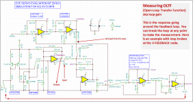
This one was less clear to me. I would have thought the Output for this would be measured at V-FEEDBACK rather than X1-5.
Dumb question. How do you know where the gain is really 1 for the real rather than theoretical system?
Attachment #1: Feed-Forward Transfer Function (FFTF)
This is the woofer SPL response measured when the input signal is applied to the mixer input but the feedback loop has been opened somewhere. It can also be described as the response without MFB. Frequently it is mistakenly called the open-loop response.
Makes perfect sense. I would be inclined to describe this as having some "pre-corrections" applied to aid in achieving the desired result.
Attachment #2: Closed-Loop Transfer Function (CLTF)
This is the woofer SPL response measured when the input signal is applied to the mixer input and the feedback loop is closed and active. It can also be described as the response with MFB.
Makes perfect sense.
Attachment #3: Open-Loop Transfer Function (OLTF)
This is the response measured around the feedback loop. To measure, you must open the loop somewhere(hence the name) and inject the input signal while monitoring the response after the signal has traversed the loop and come back to the break where you are injecting the signal. Amplifier designers usually call this loop-gain. This is the measurement that is needed to evaluate the stability of the MFB system as well the distortion reduction potential. If you would rather not break into MFB electronics to perform this measurement, you can calculate the OLTF from measurements of the FFTF and CLTF taken with the microphone in the same position. REW and most other measurement systems can perform this simple math.
OLTF = (FFTF – CLTF) / CLTF
This one was less clear to me. I would have thought the Output for this would be measured at V-FEEDBACK rather than X1-5.
Attachment #4: Phase margin is determined from the OLTF by finding the 0db crossing points; the frequencies for which gain has fallen to 1. Trace up/down to see what the phase is at these frequencies and compare it to +/-180 degrees. Remember if phase shifts by 180 degrees in the feedback loop you have created an oscillator. So, phase margin is a measure of how close the MFB circuit is to breaking into oscillation. I usually shoot for phase margin of 60deg which is nice and stable, showing only minor peaking which is easily EQ’d in the pre-amp section. If you aim for 90deg phase margin or better to avoid any peaking you will wind up with so little OLTF gain that you won’t be getting much distortion reduction. As with most engineering endeavors, compromises abound.
Dumb question. How do you know where the gain is really 1 for the real rather than theoretical system?
Hello Bolserst,
Maybe I missed something, but where does the 12 dB peak at 7 Hz in the "MFB active" transfer function come from?
Regards,
Eelco
Maybe I missed something, but where does the 12 dB peak at 7 Hz in the "MFB active" transfer function come from?
Regards,
Eelco
Hello Bolserst,
Maybe I missed something, but where does the 12 dB peak at 7 Hz in the "MFB active" transfer function come from?
Regards,
Eelco
Acceleration feedback increases the apparent effective mass and increases Q. See Post #10.
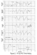
Indeed, especially the YF-22 PIO(Pilot Induced Oscillation) incident at about the 1:00 mark....I guess you are very familiar with this kind of stability issues, some of those problems was solved in the end with filters.
Feedback control systems get even trickier when you have a human as a "dynamic" filter in the loop. See attached time history of the event taken from an AIAA paper on the F-22 control system. Fortunately this issue was sorted out during flight testing of the demonstrator years before the F-22 started production.
Glad to hear you found the MFB posts helpful.
Attachments
By pre-corrections, are you talking about……I would be inclined to describe this as having some "pre-corrections" applied to aid in achieving the desired result…
(1) filters between the mixer and the power amplifier?
-or-
(2) filters in the pre-amp section upstream of the mixer; for example the rumble filter
The FFTF does include (1), but does not include (2).
Remember when measuring the OLTF, you need to measure what happens to an injected signal when it makes its way around the entire loop, not just part of it. There are small random noise signals generated all the time inside electronic components. You need to make sure that as they pass around and around and around the loop their magnitude doesn’t grow uncontrollably at any frequency.I would have thought the Output for this would be measured at V-FEEDBACK rather than X1-5.
If you want to measure at V-FEEDBACK, you would need to break the loop there and inject the signal into R15. (see attachment)
You have to measure it.How do you know where the gain is really 1 for the real rather than theoretical system?
If you calibrate REW before making the OLTF measurement, the 0dB point will be where the real gain is 1.
REW_Calibration_Soundcard
If you don't calibrate, you can make a separate measurement of the input signal and then normalize the OLTF measurement by it.
OLTF(calibrated) = OLTF(measured) / input signal(measured)
Attachments
It is a result of the low phase margin...only 20 degrees from becoming an oscillator....where does the 12 dB peak at 7 Hz in the "MFB active" transfer function come from?
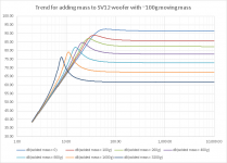
As rscamp mentioned, MFB using an accelerometer as a sensor can be thought of as adding effective mass if no filters are used in the feed-forward or feed-back paths. If you take the SVS12 woofer and measure it as you add mass, you will see the resonance frequency lower as well as the overall sensitivity(SPL), but the Q increases causing response peaking. You would need to add 3.2Kg! to get the resonance down close to 7Hz and the peaking would be more than 12dB. See response trends when adding mass shown in Attachment #1.
The equations of motion rscamp described assume ideal woofer response with no inductance and no other filters changing phase from the natural phase response of a 2nd order HP filter. The exact same response can be derived by using an ideal woofer in a MFB circuit. See Attachment #2
(A) If +30dB of gain is added in the feed-back path, you will get exactly the same response as if 3.2Kg of mass was added to the cone. Notice the SPL has dropped by -30dB because the feedback system sees the +30dB of gain as an error and compensates for it by adjusting the CLTF to have the mirror of the error(ie, -30dB instead of +30dB)
(B) IF +30dB of gain is instead added in the feed-forward path you get the same response but the SPL remains at 0dB.
In both cases the peaking behavior is the same and can be related to the phase margin at the 0dB gain point of the OLTF. Unlike the added mass experiment where the phase margin is fixed, it can be altered in a MFB system. For example...
(C) Suppose the power amplifier has a 5Hz HP filter at its input. This reduces the phase margin and peaking gets even worse.
(D) If Lag Compensation is used, the phase margin can be increased to over 60deg and essentially eliminate the peaking.
Attachments
Let me join others in appreciating Bolserst's great help, patiently explaining stuff. My grasp of MFB has now doubled: it is up around 10%.
Phase sure is an issue with speakers that have resonances within their bandpass. But if we are aiming only for 20-200 Hz*, the phase margin stays within about 90-degrees. Funny stuff outside that band is tolerable or manageable, so long as there's no oscillation.
With a microphone (sound output) sensor, we are measuring "the real thing" but the phase trace is thoroughly unmanageable.
With accelerometer feedback, we are getting a true sense of cone motion, even if not quite speaker output, at the cost of adding a sensor gizmo and it's issues.
With current or Wheatstone Bridge feedback, we are regressing to voice coil movement (sensed as back-EMF, a fallible representation of VC movement).
But is the phase trace more favourable with current feedback?
B.
* looks like bass enthusiasts are really aiming for 15 Hz or lower these days... and half of the members here can't hear well over 10k Hz.
Last edited:
Indeed, especially the YF-22 PIO(Pilot Induced Oscillation) incident at about the 1:00 mark.
Feedback control systems get even trickier when you have a human as a "dynamic" filter in the loop. See attached time history of the event taken from an AIAA paper on the F-22 control system. Fortunately this issue was sorted out during flight testing of the demonstrator years before the F-22 started production.
My mother use to work on the ejection seat for the F-22 Raptor at Teledyne.
The box is finally finished. Both channels checked out so I connected the one speaker I have functioning into the audio system for the first time to actually listen to something. It seems to be working as it should with one big exception - a lot of 60 Hz hum. It seems worse now but that could be because the listening room is a lot quieter than the workshop.
This is what happens when a mechanical guy does electronics. 🙁 I'm not sure what is wrong. I grounded the split supply COM to the aluminum chassis. Maybe I shouldn't do that? Or maybe this power supply is noisy? Or maybe I have done something dumb like installing the electrolytic filter caps backwards on the power rails? Or ???
This is what happens when a mechanical guy does electronics. 🙁 I'm not sure what is wrong. I grounded the split supply COM to the aluminum chassis. Maybe I shouldn't do that? Or maybe this power supply is noisy? Or maybe I have done something dumb like installing the electrolytic filter caps backwards on the power rails? Or ???
Attachments

- Home
- Loudspeakers
- Subwoofers
- MFB for ACI SV12 Drivers using Piratelogic Electronics