Thanks, Mark!Indoors, I tried driving just one block of 4 drivers and impulse really cleaned up vs all 24.
First is mic at mid (white trace) of line, and at plus 2ft from mid, and down 2ft from mid.
Second is mid again, with mic on ground, and even with top of line.
Third is mid again and mic 2 ft above top of line. Couldn't even find an impulse peak haha
Could you post the frequency response of the block of 4 drivers compared to the "full Monty"?
Corner Floor-to-Ceiling Line Array Using Vifa TC9
This page has some measurements at varying heights, distances, etc. Cool stuff, Mark. I haven't been following, but I'll try to peep in every now and then.
Are you going to compare curved versus straight? That'd be fantastic. Without reading through the entire thread, do you have a post where I can read about your drivers, goals, etc.?
One thing I would try is the 'expanding array' design. Basically, as you move towards the center of the array, you taper off the HF response of the individual units. For example, the whole array is providing output at 500 Hz, but by 1000 Hz, it is only the central half, then by 2000 Hz, it is the central quarter, and then higher up, maybe it can be just one driver, which can then be either a waveguided tweeter or a ribbon to control vertical directivity. This way you get constant directivity plus you don't get the combing at HF. It might also be easier to EQ in a room, I don't know. Basically follows this design:
Snell Acoustics XA Reference Tower loudspeaker | Stereophile.com
I tried to do something similar:
Corner Expanding Line Array with KEF Q100
I feel like I didn't give this one enough of a chance to succeed. But would be interesting to see what you come up with, especially because it looks like you have control over groups of units and what they are fed. The tapering is based on wavelength and distance. As the distance between the ends of the operating drivers approaches the wavelength of the frequency, you begin the taper.
If you do an "expanding" array design, it's much more efficient to use a center tapered array. Since the outer elements only end up playing lower frequencies, they don't need the same tight spacing as the inner elements. I built a center-tapered microphone array with 23 mics that managed a constant beamwidth from 200 Hz to 16 kHz or something like that. It was just over 6 feet long. There's actually a trade-off between how narrow you want to beam, and how wide of a bandwidth you need a constant response. Since localization for humans is poor below 200 Hz, I didn't need to go any lower.
I have a matlab function that generates the appropriate filtering for each mic (could equally be used for speakers) if anyone is interested. It could also be applied to a uniform array, which would be a simplification.
Here's a page on that project:
Innovative Microphone Array Proof-of-Concept - Gearslutz
Thanks, Mark!
Could you post the frequency response of the block of 4 drivers compared to the "full Monty"?
Here you go Art,
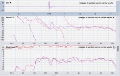
One 4-driver section (3rd section down),
raw measurement taken with array in the corner (red), and out 2-3ft from corner (blue).
Mic was only about 6ft away before I ran into pool table, so floor bounce around 360Hz.
So far, I'm not a fan of corner placement.
Freestanding, out of the corner a bit (kinda like the picts of wesayso's rig) has been making for better measurements and sound.
What's interesting and I don't yet fully understand, is why a phase wrap pops up when put in the corner (820 Hz in this plot, changes a bit depending on particular room corner, but always pop up once in corner).
I'm guessing the phase is the sum of the drivers output with corner reflections, which would increase the effective focal distance some, and make for more time lag...?
Attachments
If you do an "expanding" array design, it's much more efficient to use a center tapered array. Since the outer elements only end up playing lower frequencies, they don't need the same tight spacing as the inner elements. I built a center-tapered microphone array with 23 mics that managed a constant beamwidth from 200 Hz to 16 kHz or something like that. It was just over 6 feet long. There's actually a trade-off between how narrow you want to beam, and how wide of a bandwidth you need a constant response. Since localization for humans is poor below 200 Hz, I didn't need to go any lower.
I have a matlab function that generates the appropriate filtering for each mic (could equally be used for speakers) if anyone is interested. It could also be applied to a uniform array, which would be a simplification.
Here's a page on that project:
Innovative Microphone Array Proof-of-Concept - Gearslutz
Neat project, thx! I hope to listen to your recordings later today.
I've been thinking the biggest problem with the 'expanded array' concept with the 24 TC9's, is that a small center section of TC9's simply doesn't have the high freq SPL to keep up.
Heck, the whole dang line needs high freq lifted to begin with !
That response looks quite good for just four drivers, +/- 3dB from around 140 Hz to past 16 kHz. My 6 driver units may be OK with no EQ.Here you go Art,
One 4-driver section (3rd section down),
raw measurement taken with array in the corner (red), and out 2-3ft from corner (blue).
Mic was only about 6ft away before I ran into pool table, so floor bounce around 360Hz.
I'm guessing the phase is the sum of the drivers output with corner reflections, which would increase the effective focal distance some, and make for more time lag...?
Your corner phase wrap guessplanation sounds reasonable to me, though surprising that the upper octave, where the driver dispersion drops to only about 45 degrees would also show the same response as below. It would be interesting to see/hear what happens with "waveguides" (or pillows) from the edge of the drivers to the walls.
Art
Neat project, thx! I hope to listen to your recordings later today.
I've been thinking the biggest problem with the 'expanded array' concept with the 24 TC9's, is that a small center section of TC9's simply doesn't have the high freq SPL to keep up.
Heck, the whole dang line needs high freq lifted to begin with !
The array won't be more sensitive in the top end than a single driver due to interference in the top end.
Indoors the array will be most sensitive to reflections from parallel planes to the array. But, you'll also see a floor and ceiling array reflection not present in the outside measurements. It kinda acts as an even longer array, so don't expect to get away with an EQ scheme build up from outdoor measurements.
Look at frequency dependent gates to see what happens indoors, check for every vertical ridge what its effect is in the IR. The pillow trick that Art mentioned would be a good start.
Thanks wesayso,
Yes, please know i do not expect outdoor tuning to be a building block for indoor. (I think I grasped werewolf's great thread pretty well.)
I just always start with outdoors because it helps me separate room response from pseudo anechoic speaker response.....
Today I've been looking more closely at the response of a single section vs the entire array.
I had known there would be a lot of interference at the top end, but I'm kinda amazed at how much sensitivity improves using only 4 drivers vs all 24.
Beginning right about the wavelength of center to center spacing, a little over 4kHz, the single section maintained about a 4.5 dB advantage, as well as looking much better behaved.
Your comment help put my mind back on track...and the 'expanding array' idea looks alot more promising now.
In a couple of days I have parts coming in to help hook up dsp/amps. Then I'll look at the expanded setup and get the CBT running.
Until then. I'm going see if I can get a good picture on the room interactions you describe, and find a bunch of pillows 😀
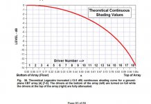
Maybe it will be useful to make a picture like this:

Adapted to your specific listening distance. It makes you 'see' which drivers are within a certain frequency range. I had ideas about an expanding array as a backup plan, meaning I did think about having the outer groups of drivers roll of at a certain frequency corresponding to their (difference in) distance from driver(s) to listening spot.
I never tried it, but it does make sense to try it as you can drive the arrays as separate groups of drivers.
If 4 drivers work so well, what do you need the rest of them for? I had that very thought listening to my single driver test box sitting on top of a subwoofer. The answer was easy to come up with: increased dynamics, low end support, vertical directivity.
In fact, the array effect of a 3db per octave roll off isn't so much a loss as a break even. For each doubling of the driver count you get 3db more power handling capacity. If the driver has a rising response you might even come out slightly ahead. You break even +/- a few db in the high end and gain lots at the low end.
For example, my 32 driver (SBC65WAC25) array model is down 15 db at 10 Khz when I use a flat driver model but with 32 drivers, there is 15 db of increased power handling. Using real measurements of a single driver in the model, the array rolloff is canceled by the driver's rising response above 3600 Hz. My equalization actually has some cut in the top half octave, but it is just a model. I have a month or so to wait until my cabinet CNC is done.
If you do an "expanding" array design, it's much more efficient to use a center tapered array. Since the outer elements only end up playing lower frequencies, they don't need the same tight spacing as the inner elements. I built a center-tapered microphone array with 23 mics that managed a constant beamwidth from 200 Hz to 16 kHz or something like that. It was just over 6 feet long. There's actually a trade-off between how narrow you want to beam, and how wide of a bandwidth you need a constant response. Since localization for humans is poor below 200 Hz, I didn't need to go any lower.
I have a matlab function that generates the appropriate filtering for each mic (could equally be used for speakers) if anyone is interested. It could also be applied to a uniform array, which would be a simplification.
Here's a page on that project:
Innovative Microphone Array Proof-of-Concept - Gearslutz
This makes complete sense. As the frequency gets higher and wavelength gets shorter, the drivers must be placed tightly together. I tried to solve it by using the KEF coaxial driver, where the 4-5" driver mates nicely with a concentric tweeter.
Your mic project is very cool. I'll remember to listen to those recordings.
Wesayso, Mark, the taper frequencies should be tied to the relative distance of drivers from the center of the array, not the listening spot. Basically, you are tying the frequencies emitted to the radiated wavelength. As you go up in wavelength (in the vertical direction along the array), you go down in the highest frequency emitted. You get nice vertical directivity, and none of the cancellation due to driver to driver distances. BTW, this is not a problem if you are about 2x length away from the array, as I showed in my measurements. Once you are that far back, the cancellations get filled in by the arrivals from other units.
Also, if you are going to put them in corners, depending on your wall configuration you are going to need different EQ from outdoors, or even indoors. There will be a huge boost in the low frequencies. And the speaker to wall interface will have to be very smooth, or you can use absorption (pillows) or OC 703.
Also, if you are going to put them in corners, depending on your wall configuration you are going to need different EQ from outdoors, or even indoors. There will be a huge boost in the low frequencies. And the speaker to wall interface will have to be very smooth, or you can use absorption (pillows) or OC 703.
I wouldn't want a single driver to be responsible for that much of the frequency spectrum, say from about 4 KHz and up. And that's taking one wavelength as the starting point. To truly act as a point source one should take even less than a quarter wave length, which is even more impossible to achieve in real life.
Taking this concept back to the listening position allows you to use more and more drivers to cover a broader part of the frequency spectrum.
That is why I would only be willing to look at a certain listening distance to determine where to cut off the outer drivers (the upper and lower ones). That way I can share the important part of the frequency spectrum(*) among more drivers. Keeping the efficiency at that particular distance to the max, while still limiting the comb effects (at that listening distance and beyond).
Reason for me to not chase any of this is that I wanted an even coverage at more than one listening height, in other words when sitting down as wel as standing up, and went for the infinite line approach as best as I could, taking its particular quirks for granted.
While there may be some merit to the theoretical expanding array it is nearly impossible to get it right in the real world (as is the infinite array, in all honesty). I would not even start with full range drivers to achieve something like this, I'd probably look at using something much like a synergy horn to form the tightly spaced base for a concept like that and let it grow from there.
My main inspiration came from looking at the work of Dunlavy, the array work done at Mcintosh, Genesis and the early full range arrays on this forum to determine my route. But I did have several backup plans (to save all that work if needed). Luckily it turned out (more than) good enough so I never needed those plans.
B.t.w. I'm not nearly at 2x array length distance from my array, then again, I did go for an infinite array approach, right? 😀. How far back would I need to be should I even remotely succeed to mimic that optimum case 😉.
There's lots of room to play with here, but getting the 'practical optimum' will never be easy. Pick your own compromises as you see fit, personally I don't regret going with a full range unshaded array and have learned a lot about why it worked.
It turned out to be more than adequate for my personal goals.
One of the biggest pitfalls is the room, to be able to make any sense of its effect on what we hear. That could completely ruin the outcome of any form you'd choose if you're not careful. And Mark did say he wanted to find/pursue the solution that needed the least alteration/modification from the room itself. In that case I still think the CBT approach could turn out to be the winner for that particular goal.
(*) I am a strong believer that most music "lives" in the mid-range. Yes I still want a solid bottom and a sweet sounding top end, but the mid-range is by far the thing I want to have right, most of all. That's what's giving me the chills down my spine... lets me have goose bumps.
No boom and tizz system for me. That simply does not stand the test of time for me, others may feel (very) different about this. Good mid-range equals magic for me.
One suggestion for mark100 is to vertically amplitude taper the CBT version to approximate a Legendre roll-off across the speaker's aperture. Assuming 6 banks of 4 drivers each for 24 drivers in his stack, I suggest that the bottom three banks (call these banks 1, 2, and 3 from the bottom upward), which are the 12 drivers closest to the floor, operate at full amplitude--say 0 dB reference. The next highest 4 drivers (bank 4) should have an attenuation level of -3 dB, then bank 5 a level of -6 dB, and finally bank 6's 4 drivers produce an level of -12 dB.
Don Keele uses a similar attenuation taper--albeit three levels--for his CBT24 speaker which uses 2.5" diameter drivers. My Modified CBT24 project follows Keele's suggestion and my speakers exhibit great sound in my listening room.
Don Keele uses a similar attenuation taper--albeit three levels--for his CBT24 speaker which uses 2.5" diameter drivers. My Modified CBT24 project follows Keele's suggestion and my speakers exhibit great sound in my listening room.
Last edited:
Hi guys, good stuff.
Yes, I get the distinction between taper frequencies based on center to center spacing, and delay timing to a specific listening spot.
My understanding is that 1/4 wave spacing of drivers is to minimize lobing over as wide a listening area as possible independent of a focus spot.
And that delay timing further minimizes lobing at a focus spot.
Using the broadest brush strokes, my further understanding is that a line array's effective boundaries are the center-to-center spacing of the VHF drivers for non-lobing VHF, and the length of the line for LF pattern control.
Pls correct any of those understandings if in error. 🙂
And then there is also the consideration of line lobing being damped at listening distances of 2x the line length.
Anyway, lots to play with, and this is exactly the learning I've been hoping for.. thanks again all..
@ra7, yes, i'm also good with the different EQs that will be needed for corner vs freestanding. I think some fabric covered OC703 wedges could work well for filling in the corners if I end up liking corner placement.
One quick question about your downloadable measurements.....
the phase traces...normally, when I see alot of phase wraps, they get cleaned up when constant delay is removed (estimated IR shift).
Your files appear to already have been shifted, but the wraps remain???? I've never seen that before.
I see that FDW removes the wraps, but I don't know REW well enough to understand what is going on..
One suggestion for mark100 is to vertically amplitude taper the CBT version to approximate a Legendre roll-off across the speaker's aperture. Assuming 6 banks of 4 drivers each for 24 drivers in his stack, I suggest that the bottom three banks (call these banks 1, 2, and 3 from the bottom upward), which are the 12 drivers closest to the floor, operate at full amplitude--say 0 dB reference. The next highest 4 drivers (bank 4) should have an attenuation level of -3 dB, then bank 5 a level of -6 dB, and finally bank 6's 4 drivers produce an level of -12 dB.
Don Keele uses a similar attenuation taper--albeit three levels--for his CBT24 speaker which uses 2.5" diameter drivers. My Modified CBT24 project follows Keele's suggestion and my speakers exhibit great sound in my listening room.
Thx Jim,
I've been planning on applying shading via the curve in PE's CBT36K assembly manual...which at quick look appears close to your recommendations.
I should have some lower powered network amps running in a couple of days, and will be able to get a first listen.
I've waited on lower powered amps cause the smallest thing I had to put on each bank was just way to big.
I don't mind blowing up a single section of 4 drivers, like I've been experimenting with so far on the straight line (a section I may have already damaged 😱 haha) ...but I'd cry if I blew the whole line.
Attachments
Did you notice that miniDSP has a 16 channel amp for $1099?
Plate Amplifiers : PWR-16
re' weighting
I would recommend taking the series approx to the Legendre curve, dropping it into a spreadsheet, and computing weights from there.
U(x) = 1 + .066x - 1.8x2 +.743x3 for x <=1
where x = drivernumber/numdrivers, starting x=0,1...
Doing this, you'll want to truncate the top few drivers For example, compute the curve as if you had 28 drivers then judge that the weights of the top 4 are so small you might as well drop them from the array. I did such a spreadsheet (attached) and with truncation, the weights Keele and Jim Griffin used started to make sense.
So convenient to just drop the weights into your DSP/amp gain. You also get to experiment with frequency dependent weighting so as not to lose any of the volume displacement needed at the low end.
Attachments
Did you notice that miniDSP has a 16 channel amp for $1099?
Plate Amplifiers : PWR-16
re' weighting
I would recommend taking the series approx to the Legendre curve, dropping it into a spreadsheet, and computing weights from there.
U(x) = 1 + .066x - 1.8x2 +.743x3 for x <=1
where x = drivernumber/numdrivers, starting x=0,1...
Doing this, you'll want to truncate the top few drivers For example, compute the curve as if you had 28 drivers then judge that the weights of the top 4 are so small you might as well drop them from the array. I did such a spreadsheet (attached) and with truncation, the weights Keele and Jim Griffin used started to make sense.
So convenient to just drop the weights into your DSP/amp gain. You also get to experiment with frequency dependent weighting so as not to lose any of the volume displacement needed at the low end.
Waay cool spreadsheet, thx !!!!
(who/what is JR 3&4 step?)
It will be very convenient to drop into dsp, indeed!
I hadn't seen the 16 channel minidsp.
I got lucky a few days ago and found a pair of QSC cx168's for $600 total w shipping.. 8ch x 90W @8 ohm. Biggest plus is they network with Q-sys.
It's going to be soo easy to experiment 🙂
https://www.qsc.com/resource-files/productresources/amp/cx/cx_series_8-ch/q_amp_cx_8ch_specs.pdf
Hey Mark,
Cool project!
Makes me want to dig out my line array again - last time I did, I had the problem of the HF balance varying with distance, which is annoying. Rolling off the HF of the bottom 3/4 of the line helped, but then heroic EQ was needed to get the response flat again.
Needs some more thought, methinks.
Chris
- Home
- Loudspeakers
- Full Range
- Line array steering ?