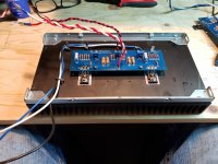
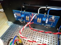
Also check that you have the ZTX450 and 550 on the correct side.
And I can't see the bottom of your PSU board: does it also have the jumpers in the middle that the top does?
And I can't see the bottom of your PSU board: does it also have the jumpers in the middle that the top does?
If no smoke came out than the most obvious things to check are -
1) Do you have the Mosfets in backward? Q4 is the 240, Q3 is the 9240
Bingo. One board has 240's, the other has 9240's. They came packaged in pairs that I thought were "matched sets", but were obviously 2 of each item.
Is this the reason I had 23V at the binding posts though? Doesn't seem right.
Also check that you have the ZTX450 and 550 on the correct side.
And I can't see the bottom of your PSU board: does it also have the jumpers in the middle that the top does?
No sir. Didn't seem necessary - or rather that is claiming a lot more understanding of the issue than I probably have - I didn't see anyone else do it. Put it that way. I do have the correct voltages at the outputs. Very incorrect ones at the right channel speaker binding posts. Haven't tested the left channel yet but may have to rebuild that one.
In fact I may just order the whole kit - boards and parts - again. Except I need to find out why I have this voltage at the binding posts first.
You should add the other ground jumper, although it won't be the cause of your issue.
Having 2 IRFP9240s in one channel and 2 IRFP240s in the other will.
Having 2 IRFP9240s in one channel and 2 IRFP240s in the other will.
Bingo. One board has 240's, the other has 9240's. They came packaged in pairs that I thought were "matched sets", but were obviously 2 of each item.
Aha! mystery solved.
Is this the reason I had 23V at the binding posts though? Doesn't seem right.
Absolutely is the reason.
there is a simple and ultrafast solution, when one by mistake did mount all N mofets to one channel and all P mosfets to other : connect all positive rails to first channel , connect all negative rails to second channel ;
tip: do not connect gnd

tip: do not connect gnd

I don’t think mighty Zen Mod is being super serious today... 😀
Thanks for the tip on the tip.
I find the easiest way is to use a solder pump (a silicone-tipped spring-loaded suction device).
Next would be solder wick (woven copper braid).
If you don't have either, you can often use multi-strand wire (with as many strands as you can find) to wick out the solder. After that you can try to wiggle it out by heating each pin in order and pushing it a bit.
Next would be solder wick (woven copper braid).
If you don't have either, you can often use multi-strand wire (with as many strands as you can find) to wick out the solder. After that you can try to wiggle it out by heating each pin in order and pushing it a bit.
Multi-pin devices can be tricky. Risk is lifting a pad, although these boards are good quality so less chance of that. A vacuum desoldering gun takes the stress out of it (Hakko 808 best purchase I ever made!). Without a desoldering gun, far easier to sacrifice the part and snip the leads so you just have to deal with single points of attachment. Just my $0.02.
BK
BK
Last edited:
so here's another quiz: When I was testing my right channel, my left channel was installed. I hadn't yet zeroed the pots. I removed the V+ wire but not the GRD123 or the V- wire. This amp board also had two 9240's installed. When I plugged it in and switched it on, there was a short delay and then I got a wisp of smoke from the left channel from approximately where the XTX 550 at Q5 is.
I obviously would like to troubleshoot this before I install it again. What is it that I've likely fried and how might I test it?
Edit: I had the (2) 240's installed on this board.
I obviously would like to troubleshoot this before I install it again. What is it that I've likely fried and how might I test it?
Edit: I had the (2) 240's installed on this board.
Last edited:
oh damn ...... this is just F5 , having what - dozen of parts for both channels !!
pull all semis out , test them
even better - test just JFets with matching jig ( 9V battery and multimeter) , throw everything else (semis) in trash and mount new ones
this time taking care of every step , using bulb tester for initial power up , channel by channel
if you're not sure what next step is - better ask here than disconnecting and connecting whatever you choose in moment of heat
oh damn ...... this is just F5 , having what - dozen of parts for both channels !!
pull all semis out , test them
even better - test just JFets with matching jig ( 9V battery and multimeter) , throw everything else (semis) in trash and mount new ones
this time taking care of every step , using bulb tester for initial power up , channel by channel
if you're not sure what next step is - better ask here than disconnecting and connecting whatever you choose in moment of heat
Okay ZM, I'm back in the saddle with all new parts triple checked twice. Lifted the 3w resistors off the board, disconnected one channel completely from the PSU, zeroed out the pots, and have my bulb tester handy. Asking advice on next move.


Trismos - input JFet checked ?
bjts?
mosfets ?
properly torqued to heatsink , no short/conductivity between drain and heatsink?
bjts?
mosfets ?
properly torqued to heatsink , no short/conductivity between drain and heatsink?
to Trismos
Very nice quality build! Continue that good way!
I have build F5T - Monoblocks 2 years ago. I love them - especially driving
my electrostatic loudspeakers. Beautiful combination.
You will like your F5 - I am pretty sure!
Mounting the Mosfets: I bend up the legs (90 degrees with a 'soft' bending)
and stick them in the pcb (pcb is mounted with standoffs on the heatsink).
Then I mark the mountinghole through the Mosfet to the heatsink. I use a
special marker pen from the company EDDING 8850 (specially made for
marking drilling holes).

Greets
Dirk

Very nice quality build! Continue that good way!
I have build F5T - Monoblocks 2 years ago. I love them - especially driving
my electrostatic loudspeakers. Beautiful combination.
You will like your F5 - I am pretty sure!
Mounting the Mosfets: I bend up the legs (90 degrees with a 'soft' bending)
and stick them in the pcb (pcb is mounted with standoffs on the heatsink).
Then I mark the mountinghole through the Mosfet to the heatsink. I use a
special marker pen from the company EDDING 8850 (specially made for
marking drilling holes).
Greets
Dirk

- Home
- Amplifiers
- Pass Labs
- Another F5 Build
