Stop, almost the full rail at the speaker post indicates a big error somewhere. As does smoke.
I believe I smoked the transistor at P1 of the Left channel because I didn't set the pots down and I neglected to take all the power wires off. Why I have issues with the Right channel I cannot tell. I checked the wiring several times over and (was) sure I had it right between the PSU and the amp. 🙁
Last edited:
Well that's enough of a let down for me tonight. The latest pics are on page 3 of this thread if anyone wants to take a look but I see nothing obvious .... obviously. Tomorrow's another day! Will figure it out eventually. Thanks for the support thus far.
I can get P1 to change voltages meaningfully at R11 and have it set at about .30 but P2 / R12 is stuck at .6 and the pot doesn't make any difference.
It looks like you are referring to a different schematics than the
version of your PCB. Please see the schematics on page 2 on
the following pdf:
http://www.firstwatt.com/pdf/art_f5_turbo.pdf
That should match with your PCB.
Dennis
It looks like you are referring to a different schematics than the
version of your PCB. Please see the schematics on page 2 on
the following pdf:
http://www.firstwatt.com/pdf/art_f5_turbo.pdf
That should match with your PCB.
Dennis
I was following the build guide pdf for the V2 for basic instructions and this is where I was mixed up with the R11 / R12. I am actually testing at R7 / R8.
Issues still: R7 is adjustable and sitting at .350 V, R8 is not and sitting at .6V and I have 23V at the speaker terminals which apparently is a very ungood thing. If there are no further suggestions, or nothing obvious determined by looking at the photos on page 3, I will probably have to rip it all apart and go over solder joints etc some time later today or this week. Disappointing. Looks so nice and tidy.
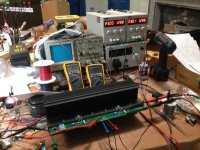
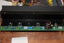
Another F5 channel is born:

~600mV bias, single-digit mV offset (-0.4mV at time of picture, but it bounces around a bit), ~65ºC MOSFET case temp.
Now if only I could learn to focus my phone camera properly.
Nice! That looks like an original ("factory" doesn't seem the right word for First Watt) F5 board and heat sink. What is the story behind that?
The boards are my own, but the "long skinny" aesthetic of the channel boards is one of the things that first drew me to FirstWatt, so I had to keep that.
My F3 boards are also similar, although there are more differences there because I have a tweeter out that bypasses the capacitors, the polypropylene is a "jelly roll" under the board, and I mounted my Lovoltech's on top where they could be seen. 😀

Cheers,
Jeff.
My F3 boards are also similar, although there are more differences there because I have a tweeter out that bypasses the capacitors, the polypropylene is a "jelly roll" under the board, and I mounted my Lovoltech's on top where they could be seen. 😀
Cheers,
Jeff.
Attachments
The boards are my own, but the "long skinny" aesthetic of the channel boards is one of the things that first drew me to FirstWatt, so I had to keep that.
My F3 boards are also similar, although there are more differences there because I have a tweeter out that bypasses the capacitors, the polypropylene is a "jelly roll" under the board, and I mounted my Lovoltech's on top where they could be seen. 😀

Cheers,
Jeff.
Very clean looking. Good work. Please post more pics as you progress.
Holy cow, does this thing stomp. The bass on my little Gale 4 test speakers has never sounded so good.
I initially thought it was too clinical. Who would have guessed there was so much distortion in Adele's guitar pickup? And do I really want to hear it that clearly?
But I couldn't tear myself away. It has a level of engagement I haven't experienced before. For me it was the very definition of foot-tapping. Listening to some cleanly-mastered Madonna I nearly got cramps in my calves.
I do prefer the F3 for quiet listening. It's not nearly as in-your-face. It has that feel-good warmth that humming gives you. But it bogs down a bit when things get complicated or congested.
The F5 on the other hand seems like it grows you a new set of ears for each instrument. It doesn't know what complicated or congested is. It can be breath-takingly clean.
Pictures to follow. I'm going to go listen to some more music....
That's a very concise and accurate description of the sound. All that detail and no sacrifice of the Class-A magic and pure musicality.
Forgot to mention: I used a 240V primary and my supply is only about 220V, so my rails are +/-21V.
I bumped the bias up to 680mV, which should be 1.45A and get me back to 30W at idle. Transistor case temp is stable at 65ºC.
I bumped the bias up to 680mV, which should be 1.45A and get me back to 30W at idle. Transistor case temp is stable at 65ºC.
Ugh! And me stuck taking mine apart over the weekend to diagnose "issues".
But yes, pics please!
But yes, pics please!
@JeffYoung, does your F5 implementation have the added pot (P3) to adjust 2nd vs 3rd order harmonics?
I know that people are using distortion analyzers and/or deep notch filters to display residual harmonic distortion for adjusting P3 on the F5 and BA3, but is it possible to go by the straight FFT output for people who don't have anything other than ARTA and a sound card (for example)? Can you go based on the relative values of 2nd and 3rd in the FFT?
I know that people are using distortion analyzers and/or deep notch filters to display residual harmonic distortion for adjusting P3 on the F5 and BA3, but is it possible to go by the straight FFT output for people who don't have anything other than ARTA and a sound card (for example)? Can you go based on the relative values of 2nd and 3rd in the FFT?
Replace suspect (smoky) Mosfets
I don't believe it was the Mosfet but rather the ZTX 550 at Q5 on the left channel. I had the V+ power wire off of the board but not the 2 other ground wires so I don't know why there would have been an issue anyways. BUT, as you know, I had 23V or so at the speaker terminal when testing the right channel AND I believe that 23V was at the negative terminal so it may have crossed that way.
So. I have to figure out why I have voltage at the speaker posts.
I have pulled my amps and I am looking carefully at the right channel. The parts appear to be all correct. The solder joints all appear tidy and proper. I re-measured the pots at R5 & 6 and have them set at .02.
I wired the amp board power wires to their corresponding terminal on the PSU board, so V+ (Blue in my case) to V+, GND (White) to GND 123, and the V- (Black) to the V-.
How is it possible I could have 23V at the speaker binding posts?


I wired the amp board power wires to their corresponding terminal on the PSU board, so V+ (Blue in my case) to V+, GND (White) to GND 123, and the V- (Black) to the V-.
How is it possible I could have 23V at the speaker binding posts?
If no smoke came out than the most obvious things to check are -
1) Do you have the Mosfets in backward? Q4 is the 240, Q3 is the 9240
2) Do you have the bias pots turned all the way down. If I recall on this board one of them turns backwards, (maybe...?) and that's also going to depend on which way you stuffed them. Measure across R5 and R6 and turn associated pot until you get minimum ohms.
3) Disconnecting only V+ is not removing power from the amp PCB. You have to remove all three PSU wires. Amplifier "GND" is actually the middle of two 24 supplies connected in series. You could as easily take your exact PSU and make it a 0-48V supply merely by changing where you connect the wires on the PSU output.
- Home
- Amplifiers
- Pass Labs
- Another F5 Build