I don't know on which rail voltage Trismos is running his F5.
+ / -24 V ?
+/- 32 V ?
Greets
Dirk
+ / -24 V ?
+/- 32 V ?
Greets
Dirk
I didn't want to confuse anybody. Sorry!
This is F5 not F5 Turbo.
So 600mV over 0.47 Ohm resistor would be around 1.3 A.
I apologize!
Greets
Dirk
This is F5 not F5 Turbo.
So 600mV over 0.47 Ohm resistor would be around 1.3 A.
I apologize!
Greets
Dirk
From Nelson in an earlier discussion on how hard you can push your F5 --
Technically, the junctions of the devices are rated at 150 deg C. If you are
running as high as 50 watts per device, then you will want to measure well less
than 100 deg C on the case (you can use a cheap Radio Shack IR thermometer).
Don't expect them to have a long life span at those figures, but I have seen
reasonable reliability at 25 deg less junction temp.
***
At 700mv bias my case runs only about 46c.
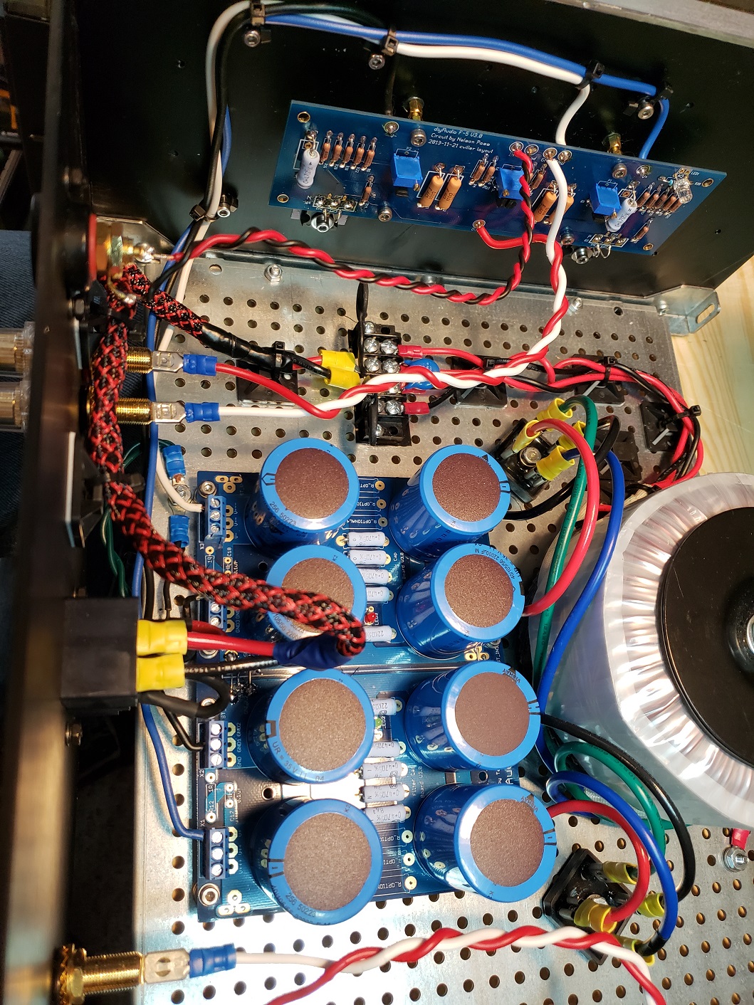
Okay DIY sleuths. I've managed to get smoke again despite taking great care, so the lessons are still being learned. I will include pics but the story first: Instead of trying to pull parts and test them - and yes I know, there's all of 30 odd parts - but I ordered two new boards along with the F5 kit and two new Jfets and took extreme care putting things where they are supposed to be, soldering everything as neatly as possible and running all my wires just so.
With help from Dirk, Jim, and the rest of you I came to understand how to properly test everything with the light-bulb tester, and this morning I was ready to give it a go. I had my outer trim pots zeroed (or as close to it as it would go at .3 ohm), and the center pots at approximately halfway - I turned these 30 full rotations click to click and then brought them back 15 and started on the right channel PCB with the left one completely disconnected.
I plugged the amp into the tester and hit the switch and the light bulb came on - no too bright at all for a 100 watt bulb - and so did the PCB LED, and after about 5 nervous seconds the bulb went out. Everything appeared just fine 🙂 So I unplugged everything and waited for the LEDs to go out, pulled the right channel wires from the PSU and installed the left channel wires. I Looked at it for a minute or so which didn't seem to do me any good so I plugged it in again and hit the power switch. The light came on about the same dimness as before but then I heard a little pop and got smoke from the middle pot / Jfet area so I shut it down.
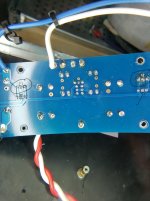
I have since taken the board off the heat sink to investigate. The soldering on the bottom of the board is good. I don't know if you can measure the 201 trim pot attached the way it is bit it reads 8.5 ohms from the center pin to either outside pin.

The Jfets are correctly installed - J74 in P channel and the K170 in the N channel BUT, it's obvious that the K170 has blistered.

J74 and the trim pot APPEAR ok with what looks like maybe a bit of residue from the smoke show.

Here's the board as it was installed just before, erm, lighting it up.


And here are some pics to verify the parts are where they are supposed to be


If anything obvious pops out it's totally managed to slip by me - mind you I'm one of the guys that missed the gorilla on the basketball court in the video on how the mind works - so there's that.
As always, your advice and even the occasional jest (ZM) are very much appreciated.
Dave
With help from Dirk, Jim, and the rest of you I came to understand how to properly test everything with the light-bulb tester, and this morning I was ready to give it a go. I had my outer trim pots zeroed (or as close to it as it would go at .3 ohm), and the center pots at approximately halfway - I turned these 30 full rotations click to click and then brought them back 15 and started on the right channel PCB with the left one completely disconnected.
I plugged the amp into the tester and hit the switch and the light bulb came on - no too bright at all for a 100 watt bulb - and so did the PCB LED, and after about 5 nervous seconds the bulb went out. Everything appeared just fine 🙂 So I unplugged everything and waited for the LEDs to go out, pulled the right channel wires from the PSU and installed the left channel wires. I Looked at it for a minute or so which didn't seem to do me any good so I plugged it in again and hit the power switch. The light came on about the same dimness as before but then I heard a little pop and got smoke from the middle pot / Jfet area so I shut it down.
I have since taken the board off the heat sink to investigate. The soldering on the bottom of the board is good. I don't know if you can measure the 201 trim pot attached the way it is bit it reads 8.5 ohms from the center pin to either outside pin.
The Jfets are correctly installed - J74 in P channel and the K170 in the N channel BUT, it's obvious that the K170 has blistered.
J74 and the trim pot APPEAR ok with what looks like maybe a bit of residue from the smoke show.
Here's the board as it was installed just before, erm, lighting it up.
And here are some pics to verify the parts are where they are supposed to be
If anything obvious pops out it's totally managed to slip by me - mind you I'm one of the guys that missed the gorilla on the basketball court in the video on how the mind works - so there's that.
As always, your advice and even the occasional jest (ZM) are very much appreciated.
Dave
Last edited:
Wires from PSU V- is connect to amp board GND, and the PSU GND is attached to V- at the amp.
🙁
Looks like Murphy got you since you used white for the speaker ground.
That garsh dangged Murphy! Hate him.
🙁
Looks like Murphy got you since you used white for the speaker ground.
That garsh dangged Murphy! Hate him.
to TRISMOS
I can feel your pain! Being so close.
And new matched JFets necessary... + work/repair - damn!
Doublecheck your wiring from PSU to mainboard - electronics don't forgive
mistakes - most often - my experience.
And clean your boards from the solderflux and solderchips / -drops!
Especially between the legs of the JFets and trimpots - they are very close to each other - good chance of shorts.
And: Don't give up! You are so close to a working F5.
Greets
Dirk
Attachments
It appears you have v minus (neg) connected to ground on the amp pcb. And ground connected to v-.
Last edited:
Yeah ... so that gorilla got me good! 😉
I purposely used white there for ground too as 6L6 noticed I used it for the speaker ground - I just happened to have some quality hook up wire in Red and White -
so how I managed to mix it up..... well whatever the case, I did. I'm a little worried that though I didn't appear to damage the Jfets in the other channel, I may have as I did the exact same thing sans the smoke. So before moving forward I will try and get a new set.
Thanks for the help as always,
Dave
you want me other set of boards or can you just buy new parts
Hey Jon
No I'm good thanks. Jason sent me another set of JFets. I'm not sure when I'm going to get around to it though my friend. I live in Northern Canada and we really only see 4 months of summer and guess what? It finally showed up. So I've got the camper to shake out, a Harley to tune up, a shed to clean out so I can build another shed and a long assortment of projects including some acoustic panels and maybe a diffuser, a deck to stain, golf to golf, etc etc etc! 🙂
That and my man room faces north west and right now we are getting 18.5 hours of sunlight... so its uncomfortably warm in there. I know you were cheering for me and I appreciate the help and all, but I'm 58 and sometimes I get to feeling like I'm running out of summers.
I'll post soon enough.
Kind regards
Dave
I had to look up your city, wow! Enjoy summer. Extraordinary YK | Yellowknife will light up your life
Interesting how it get's a little more difficult to press the power button with each failure but it lives!

I have a question about my multi-meter readings though. I'm supposed to be seeing 0 on all three but I may not have the older one set to the correct range. The Fluke and auto-ranging Mastercraft are hooked up to R7 & R8 and the older Mastercraft is on the speaker terminals.

I looked on-line for the information but still aren't sure so am heeding some advice and asking - do I have it set right for the range?
Please advise and much appreciated
Dave
A quick edit - I see in the pic that the Fluke is reading AC but I did change it to DC.
I have a question about my multi-meter readings though. I'm supposed to be seeing 0 on all three but I may not have the older one set to the correct range. The Fluke and auto-ranging Mastercraft are hooked up to R7 & R8 and the older Mastercraft is on the speaker terminals.
I looked on-line for the information but still aren't sure so am heeding some advice and asking - do I have it set right for the range?
Please advise and much appreciated
Dave
A quick edit - I see in the pic that the Fluke is reading AC but I did change it to DC.
Last edited:
Your old Mastercraft is reading 4mV, which is fine. It'll read mV on either of the lower two scales; the difference is whether or not you get a decimal point. (The higher one would show 004 instead of 04.2.)
Well, I have to travel tomorrow so I'll be shutting it down for a few days. Leave a few pics for comments here. I found these excellent isolation feet for the amp at Baosity 4 Pack Aluminum Speaker Spike Shockproof 50x15mm Isolation Feet Stand Cone Pad Turntable Amplifier CD DAC Recorder Black: Amazon.ca: Electronics


Now as for the amp, I've had the right channel running for about 45 minutes now at about 260 mv and whatever the offest appears to be on the Fluke - not enough resolution to see what it actually is so I'll grab another one later. It is NOT getting warm. The laser thermometer reads the mosfets at around 33C. My hand is 36....


Comments?
Now as for the amp, I've had the right channel running for about 45 minutes now at about 260 mv and whatever the offest appears to be on the Fluke - not enough resolution to see what it actually is so I'll grab another one later. It is NOT getting warm. The laser thermometer reads the mosfets at around 33C. My hand is 36....
Comments?
Will the bias not turn up anymore?
Per Cubicincher's instructions I trimmed them until I saw about 250-60 and let it cook.... which it never really did. Then he advised: "After a few days you should be able to bias the amp higher. Values of 300mV to 400mV over the bias resistors should be possible."
It did seem like I had a fair amount of room to increase the values but I didn't go there.
Last edited:
- Home
- Amplifiers
- Pass Labs
- Another F5 Build