Hi Trismos,
Cubicincher was speaking about the F5 turbo, which has more output mosfets.
For the F5, you can target for about 0.6V over the 0.47 ohm resistors (bias
current of around 1.3A).
Cheers,
Dennis
Cubicincher was speaking about the F5 turbo, which has more output mosfets.
For the F5, you can target for about 0.6V over the 0.47 ohm resistors (bias
current of around 1.3A).
Cheers,
Dennis
to TRISMOS
Dennis Hui is right.
If your target is 600 mV (0.6 Volt) then you can bias your F5 as a starting point to 0.45 Volt (450mV). Always watch your offset at loudspeakeroutput. Then let it cook for 30 minutes (because your 'baby' will become warmer!). Check the heat on the FETs and always keep an eye on your DMMs! Don't go away from the amp - watch your DMMs and temp!
I am sometimes overcautious! But I want to avoid that your values or heat is
running away.
No burning amp anymore! 😉
Greets
Dirk
Thanks Dirk! Will give it a whirl tomorrow night.
Dave
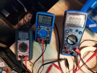
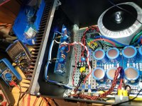
Here's the latest pic with a different DMM on the speaker posts. What am I looking to do or avoid with the reading there?
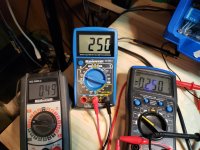
These were the readings when I first powered up. After about 5 minutes R7 & 8 are at 259 and the posts are at 65
Set it higher and adjusted to get 0 at the terminals.
View attachment 760980
Thx
Dave

These were the readings when I first powered up. After about 5 minutes R7 & 8 are at 259 and the posts are at 65
Set it higher and adjusted to get 0 at the terminals.
View attachment 760980
Thx
Dave
Last edited:
Looking great!!
Set the bias to read 0.55 across the resistors with zero offset and do the other channel.
When that one is biased and happy, place the lid on the top and wait 1/2hr.
Then check it again, if things haven't drifted off into the weeds set 0.6 across the resistors with zero offset, screw the lid on and then play some Shpongle.
Looking great!!
Set the bias to read 0.55 across the resistors with zero offset and do the other channel.
When that one is biased and happy, place the lid on the top and wait 1/2hr.
Then check it again, if things haven't drifted off into the weeds set 0.6 across the resistors with zero offset, screw the lid on and then play some Shpongle.
Are we more concerned with the offset being zero or the bias reading the same for both resistors?
Zero (or close, it will jump around a touch) offset.
If your N and P channel biases are the same, that's just lucky. They are usually a bit different, which is normal.
If your N and P channel biases are the same, that's just lucky. They are usually a bit different, which is normal.
Hello Trismos,
your values looking very good so far. Keep the offset at loudspeaker posts as low as possible (will fluctuate a bit - up and down - thats normal).
My values at the bias- resistors are always a bit different (difference between the
P-channel - and N-channel- MOSFETs).
For example: you get the loudspeakeroffset to 0.5mV - your values at the bias resistors will be anywhere around 450 mV and 460mV - perhaps better/closer.
You will listen to beautiful music pretty soon. But don`t get into a hurry! 😉
Greets
Dirk
450mv isn't enough, bias it to 600 at a minimum.
600 minimum.... what determines maximum then, heat correct? With the given layout and optimal heat dissipation, what is the maximum viable offset?
Thx
Dave
Per Nelson:
*****
Technically, the junctions of the devices are rated at 150 deg C. If you are
running as high as 50 watts per device, then you will want to measure well less
than 100 deg C on the case (you can use a cheap Radio Shack IR thermometer).
Don't expect them to have a long life span at those figures, but I have seen
reasonable reliability at 25 deg less junction temp.
*****
I run at 700mv easily and others have gone higher.
*****
Technically, the junctions of the devices are rated at 150 deg C. If you are
running as high as 50 watts per device, then you will want to measure well less
than 100 deg C on the case (you can use a cheap Radio Shack IR thermometer).
Don't expect them to have a long life span at those figures, but I have seen
reasonable reliability at 25 deg less junction temp.
*****
I run at 700mv easily and others have gone higher.
Max offset is zero. (Again, it does wander, but you need to be able to zero it out.)
0.60v bias really is the sweet spot in sound with this amp. Less and it's (mildly) audible, more and it just gets hotter.
0.60v bias really is the sweet spot in sound with this amp. Less and it's (mildly) audible, more and it just gets hotter.
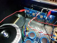
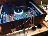
So yet again I seem to be having an issue. I have hooked up the left channel exactly as I had the right channel but I am getting no readings from R7 or 8. Nor is the speaker terminal value changing. The LED is on, and I have +22 ish between V+ and GND and -22 ish between V- and GND. turning either trim pot nets me no changes anywhere. I have turned each 10 full turns without any of the DMMs responding and I don't want to go further.
Gads.
When I finally get this sucker going, this whole post is going to be a gold mine of what to watch out for.....
Advice on trouble shooting?
Dave
Gads.
When I finally get this sucker going, this whole post is going to be a gold mine of what to watch out for.....
Advice on trouble shooting?
Dave
I have checked that R5 and R6 are changing as they are supposed to and had them zeroed out before starting.
What voltages are you seeing across R5 /R6? They need probably to be over 3.5V
before you will see voltage across R7/R8
before you will see voltage across R7/R8
What voltages are you seeing across R5 /R6? They need probably to be over 3.5V
before you will see voltage across R7/R8
I see .284v on R5 and don't seem to have anything at R6
I see .284v on R5 and don't seem to have anything at R6
So you don't have enough voltage to turn on the mosfets. 🙁
And this is after you've turned P1 and P2 a number of times? What
resistances are you seeing across R5 and R6?
What resistances/voltages do you see across R3 and R4?
- Home
- Amplifiers
- Pass Labs
- Another F5 Build
