When you replaced 2SC2240 and 2SA970, were these transistors from the same supplier as the first pairs and are you sure these are the originals and not fake ones?
Or I also read something about using the ksc1845/A992 in matched pairs.
I have got 200 of each if matching them somehow would solve my problem.
Last edited:
Lift the pot end of the 20K resistor, connect the free end of the resistor to 0V.
1. What is the new wiper voltage range of the pot?
2. What is the dc offset voltage?
I was wondering if changing my transistors to 2SA1312BL/2SC3324BL would help.
Lift the pot end of the 20K resistor, connect the free end of the resistor to 0V.
1. What is the new wiper voltage range of the pot?
2. What is the dc offset voltage?
Done som more measurements at speaker I get .016v with centre of pot to 0v.
At top of pot I get -3.04v
Bottom of pot I get -6.6v but this is with pot turned fully anti clockwise.
Have you tried this!
You all probably have done this already, and sevaral times as well: Check all the resistor values one more time.
With a friend of mine I was building the Pass Aleph 5 amplifier. My friend was hitting the wall with his amps, the same symptoms showing on both channels.
We discussed and looked at the diagrams and back to the boards with no luck. In the end I took the PCB, my friend took the BOM and then we checked all the resistors, reading the values AND colour codes out loud. And there it was, a 1% resistor with multiplier ring being RED instead of ORANGE.
Today the Alephs are finished and plays just fine!
Errors repeating itself on 2 boards are probably man-made. Like component values, switching NPN and PNP, turning transistors 180 degrees, earth loops.... (I won't even mention once I forgot the transformer when I hooked up an amplifier for testing. I checked "all" connections and tried again. Lights out again. Now I am very catious about the transformer...)
Good luck!

...at speaker I get .016v with centre of pot to 0v.
At top of pot I get -3.04v
Bottom of pot I get -6.6v...
That proves the amp is ok, it should be simple to fix the bias chain.
Refer back to the pic in post #9091
?+V should be about +1V
?-V should be about -1V, both wrt 0V.
Last edited:
Alternativly, the lifted end of the 20K resistor (pot end), connect permanently to 0V.
Anything below 0.02V is ok.
...at speaker I get .016v with centre of pot to 0v...
Anything below 0.02V is ok.
This is where your fault is.
If the pot is set to centre position the wiper should read 0V (meter black lead connected to 0V).
Refering to the pic, D1 & D2 each drop about 1V, the diodes centre connection is nailed to 0V; looking at the divider chain (2x 4K7 + 5K pot) across the diodes, the pot is aprox 1/3 of the total resistance - meaning that the pot wiper will see 1/3 of 2V or -0.66V to +0.66V (roughly).
Hi itsmee thanks for your help but I am still confused D1 is 4144 diode on +48v line I get +.55v one side of this diode and +0.0v other side.
D2 27v z diode I get +26.7v one side of diode 0v other side.
D3 diode is 4144 diode -48v line I get -46.7v one side of diode and -9.3v other side of diode.
D4 is 27v z diode I get 26.7v one side of diode and ov other side of diode.
Is it my diodes which are wrong 4k7 resistors / 9k1 resistors or ksa1845 /2sa992.
Resistors are correct by the diagram though or should I try some 2SA1312BL/2SC3324BL smd transistors.
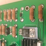
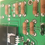
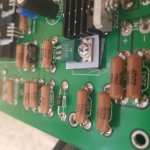
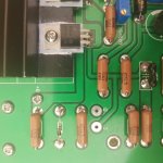
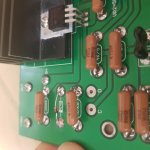
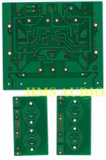
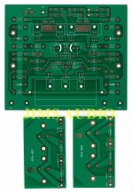
Pictures Dave, pictures 😉
Pictures where we can see the values of installed components.
Thanks neychi I did check every resistor with a meter as well and all seem to be ok.
Attachments
D1, D2 & D4 are correct, replace D3....D3 diode is 4144 diode -48v line I get -46.7v one side of diode and -9.3v...
Thanks m0rten, I did do the transistors in wrong possitions at one point pnp & npn in wrong possitions.You all probably have done this already, and sevaral times as well: Check all the resistor values one more time.
With a friend of mine I was building the Pass Aleph 5 amplifier. My friend was hitting the wall with his amps, the same symptoms showing on both channels.
We discussed and looked at the diagrams and back to the boards with no luck. In the end I took the PCB, my friend took the BOM and then we checked all the resistors, reading the values AND colour codes out loud. And there it was, a 1% resistor with multiplier ring being RED instead of ORANGE.
Today the Alephs are finished and plays just fine!
Errors repeating itself on 2 boards are probably man-made. Like component values, switching NPN and PNP, turning transistors 180 degrees, earth loops.... (I won't even mention once I forgot the transformer when I hooked up an amplifier for testing. I checked "all" connections and tried again. Lights out again. Now I am very catious about the transformer...)
Good luck!
In my difference I got the part numbers muddled up as they was not original part numbers.
Also managed to have my b+ terminal move and touch -48v blowing my output stage and some resistors.
I have removed one side of each transistor and measured it with a meter just to make sure they was reading correctly.
As you say its strange that both my boards have exactly the same problem.
Its probably something I have done wrong and will feel stupid when I find it.
The -9.3V end of the diode should be 0V, check the continuity of D3 anode (top end in schematic) to 0V.
Dave, did you put the insulation between the heatsink for MJE devices and the contacts on the board?
The -9.3V end of the diode should be 0V, check the continuity of D3 anode (top end in schematic) to 0V.
Thankyou again itsmee you are correct my D1 D3 have not got 0v to them.
I have checked all solder joints but nothing is faulty.
Should I run a wire to these diodes from 0v ground in.
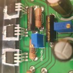
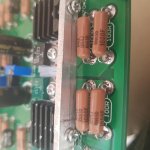
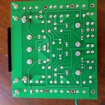
As you can see both boards have a make do joint from diode to -48v I did not do this they come like that.
Dotted line is the diodes
Attachments
Last edited:
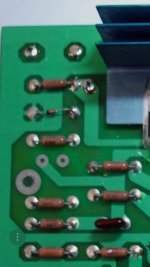
The PCB should be plate through hole; D3 0V connection, does the soldeded pad on the bottom connect to the 0V groundplane on the top? soldering topside should fix it.
- Home
- Amplifiers
- Solid State
- Krell KSA 50 PCB