Take a look at the solder joint on the bottom 1N4148 diode. There could be a solder bridge that should not be there under all that excess solder.
Take a look at the solder joint on the bottom 1N4148 diode. There could be a solder bridge that should not be there under all that excess solder.
Thanks decen bottom of 1N4148 diode on -48v side on both boards had this solder joint on when I recieved them.
I think it is correct otherwise that diode is fixed to nothing.
Thank you itsmee decen and neychi
I think it is how itsmee sugusts on #910 page 910
My diodes should be tied together with 0v in the midle.
It does seem strange that they have made such a big mistake on this pcb thats why I am double checking before I go adding ov ground wires to my board.
I think it is how itsmee sugusts on #910 page 910
My diodes should be tied together with 0v in the midle.
It does seem strange that they have made such a big mistake on this pcb thats why I am double checking before I go adding ov ground wires to my board.
Attachments
The -9.3V end of the diode should be 0V, check the continuity of D3 anode (top end in schematic) to 0V.
Hi itsmee sorry you must be sick of me and my amp.
My question is -48v diode is connected wrong I think but need to double check with you first.
If I put 0v to -9v side of diode it will be wrong side of diode I think but not sure.
What if that dodgy looking connection is not meant to be on my boards and is meant to go to 0v.
I left the solder link in place on both boards because I thought it was correct at the time otherwise this diode went to nothing.
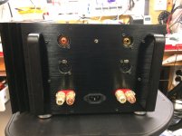
See picture its linked at back of pcb to -48v and looks like a bodge.
Does this sound right to you.
If you connect your meter with reference to gnd. you should measure around +(0.6-0.7V) over D1 and around minus (0.6-0.7V) over D3.
Last edited:
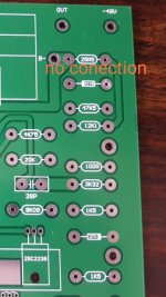
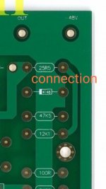
On your board connection is on solder side but it should be on component side. Look at the pictures, first is your board.
Yes I think thats what wrong you saying that they have linked it the wrong side.
The PCB should be plate through hole; D3 0V connection, does the soldeded pad on the bottom connect to the 0V groundplane on the top? soldering topside should fix it.
Thank you itsmee I am going to remove solder link bottom side and put to top side this makes more sense by the diagram you sent me.
Thank you for all your help I would never of worked it out by myself.
when I get it working you are more than welcome to come round to try amp.
I'm glad you got there in the end 🙂
It's been a long time since I listened to a Krell, I've been enjoying Pass designs for the last 10 years 😀
It's been a long time since I listened to a Krell, I've been enjoying Pass designs for the last 10 years 😀
Any PCB"s available for this project?
Hi,
I'm new to this forum. I didn't see any sticky's at the front of the thread--are there any PCB's still available for this project. I am looking to do an Amp build (first time) and this one looks very interesting.
Thanks!
Hi,
I'm new to this forum. I didn't see any sticky's at the front of the thread--are there any PCB's still available for this project. I am looking to do an Amp build (first time) and this one looks very interesting.
Thanks!
KSA-50 double cloned crash
Hello all After reading about the KSA-50 I decided to build one. I found parts and kits on the web and here it is! However, I cannot get the pcb to work.
From start it draws a lot of current as if shorted circuits. I started with low and at the end >5Ax2 at about -7V/+12V. Finally tried with the SMPS that blew up including house main fuse...
Nothing burnt on the pcb as I can see. I have studied thousands of comments and tried to learn from those ( at the age 66 😉). However the shorted circuit reduce measurements to only resistance and diod checks.
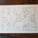
The pcb is a clone with driver and output integrated in one piece. The schematics follow the clone by Jan at Delta Audio and re-cloned by Liuxinyou in year 2010. See link ?KSA50??????DALE????????????MJL4302/4281-???
Please anyone, help me get this to work!
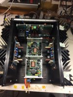
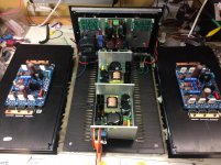
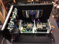
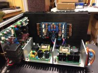
Some tech details about the package you see:
Hello all
After reading about the KSA-50 I decided to build one. I found parts and kits on the web and here it is! However, I cannot get the pcb to work.From start it draws a lot of current as if shorted circuits. I started with low and at the end >5Ax2 at about -7V/+12V. Finally tried with the SMPS that blew up including house main fuse...
Nothing burnt on the pcb as I can see. I have studied thousands of comments and tried to learn from those ( at the age 66 😉). However the shorted circuit reduce measurements to only resistance and diod checks.
The pcb is a clone with driver and output integrated in one piece. The schematics follow the clone by Jan at Delta Audio and re-cloned by Liuxinyou in year 2010. See link ?KSA50??????DALE????????????MJL4302/4281-???
Please anyone, help me get this to work!
Some tech details about the package you see:
- Unbalanced/balanced inputs via AMB lab alfa24
- Kubota PSU
- Speaker protection connected to SMPS
- SMPS 500VA soft start, +-45V, 8A peak.
- Relay switched mains
- VU meter kit ( probably not compatible w Pass Lab meter...)
- Alu box 17kg Pass Lab look
I'm glad you got there in the end 🙂
It's been a long time since I listened to a Krell, I've been enjoying Pass designs for the last 10 years 😀
Thank you I have just got to make the other one and a pre amp.
I have got this playing through both speakers in mono with a cheap volume pot at moment.
Bias is a bit up and down I am using 3 pairs of output transistors mJ21194G 312ma / mj21194g 253ma /mj21194g 263ma -
mj21193g 316ma/ mj21193g 258ma/mj21193g 276ma across 0.5 ohm resistors.
Temperaturs after 2 hours range from 59c back of hottest transister.
45c back of coldest transister hottest part of heatsink is 57c next to hottest transister and 30c near fans.
Thanks again.
Got it!
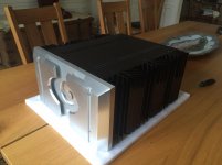
Wow that looks really well made super build quality.
I did look at nelson pass clones but they seemed a bit complicated.
I read transistors needed matching also recomended a oscilloscope a bit much for a first build.
I wouldn't have a clue how to use an oscilloscope.
KSA-50 double cloned crash cause 1
Thanks for the positive comments about the design, that actually helped me. No, this is not sarcasm .
.
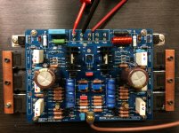
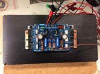
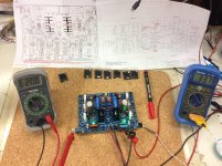
It made me look at my own photos and admire the work. A close up of the pcb and ... there it is, the root cause 1😱. Power NPN and PNP have switched positions. You can look at it yourselfes.
Lesson to learn from the pro's at this forum. Start to look at the obvious things that can go wrong. I bought this assembled a year ago and now it's to late.
I still need help to get it to work or maybe a comment to buy another populated pcb?
Thanks for the positive comments about the design, that actually helped me. No, this is not sarcasm
. It made me look at my own photos and admire the work. A close up of the pcb and ... there it is, the root cause 1😱. Power NPN and PNP have switched positions. You can look at it yourselfes.
Lesson to learn from the pro's at this forum. Start to look at the obvious things that can go wrong. I bought this assembled a year ago and now it's to late.
I still need help to get it to work or maybe a comment to buy another populated pcb?
Attachments
Thank you I have just got to make the other one and a pre amp.
I have got this playing through both speakers in mono with a cheap volume pot at moment.
Bias is a bit up and down I am using 3 pairs of output transistors mJ21194G 312ma / mj21194g 253ma /mj21194g 263ma -
mj21193g 316ma/ mj21193g 258ma/mj21193g 276ma across 0.5 ohm resistors.
Temperaturs after 2 hours range from 59c back of hottest transister.
45c back of coldest transister hottest part of heatsink is 57c next to hottest transister and 30c near fans.
Thanks again.
Your spread of tolerance is too great on your ouputs devices with .5 ohm emmiters
If you purchased these from the same lot, a 10% spread would be an acceptable
tolerance
...From start it draws a lot of current as if shorted circuits...
First thing first, are the SMPS PSU's functionong correctly? disconnect from the amp and test with load resistors, about 0.5A will do (~50V/100R=0.5A @ 25W).
Pre built single supply SMPS can cause problems from a common ground point when building a symmetrical supply, but yours look like dual output (+0-) and dual mono - one PSU per amp?
Do you have or can you get access to a 'Lab power supply' or a dual variable PSU with pre-settable current limmit?
Turn the bias down, power one amp at a time, find the faulty one (both?), If you purchased them as pre built modules, contact the seler.
If not, scrutinise every solder joint, component value* and orientation, check the resistors and semiconductors** with a mutimeter check the caps for shorts*, semi's on diode range; the resistor values may be inaccurate due the surrounding circuitry - alway lower, never higher. That will probably use most of your weekend up.
*Manufacturing faults.
I have had incorrectly marked (colour coded) resistors before, Iv'e also had faulty brand new short circuit electrolytic, tantalum, polystyrene and polyester capacitors. Don't forget the circuit board, they can be faulty too as Dave M can testify.
**There are a lot of fake components out there, did you buy yours from a reputable supplier?
Let us know what you find, or just ask more questions.
Tip of the day, old 1KW electric bar heaters (open element) can be easily converted (tapped) for use as high power load resistors, also handy as dummy speaker loads

I see you found it, you posted while I was still typing

Last edited:
- Home
- Amplifiers
- Solid State
- Krell KSA 50 PCB