hoping I did this correctly?....
Hi Mazza,
You did indeed - your design is now being modelled correctly.
Kind regards,
David
Attachments

If you're planning to fold that TH into a rectangular box, the segments should be Parabolic, not Conical, segments.
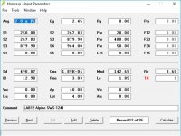
Thank you Brian. Yes I did change this last time you mentioned it a few posts back. For the record here is my input screen as it stands right now.....
Attachments
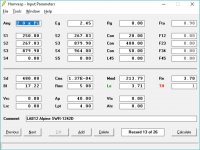
Thank you Brian. Yes I did change this last time you mentioned it a few posts back. For the record here is my input screen as it stands right now.....

Those segments are Conical ("Con") not Parabolic ("Par").
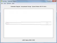
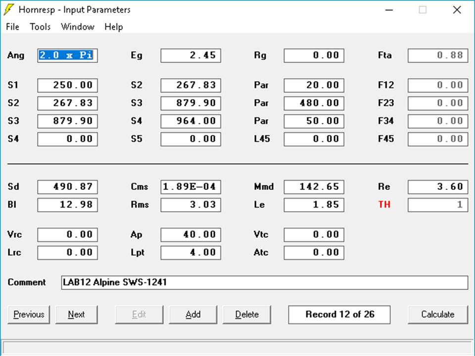
Lab12 Snyder horn with Alpine SWS-1241
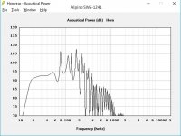
This looks great too, yes? No Semi-inductance in this one, just manufacturers spec....
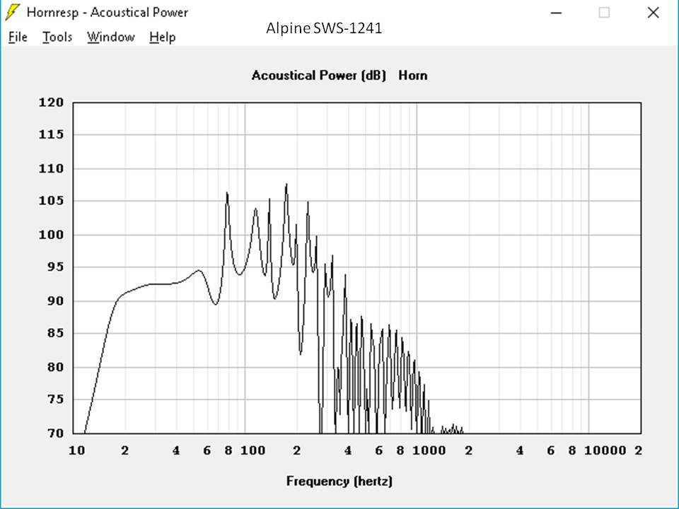
Is there anything not to like about these Alpine 12's in this box? To me they look great, yes?
This looks great too, yes? No Semi-inductance in this one, just manufacturers spec....
Is there anything not to like about these Alpine 12's in this box? To me they look great, yes?
Attachments
Those segments are Conical ("Con") not Parabolic ("Par").
Rushing! Apologies 🙄🙄
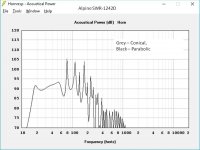
Seems to make little difference....???
Attachments
Is there anything not to like about these Alpine 12's in this box? To me they look great, yes?
Those 10dB peaks outside of the passband are going to amplify any distortion produced by the build, but the FR looks pretty decent.
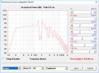
For comparison purposes, here's the sim'd response of an offset TL using the same driver (semi-inductance not enabled). SPL level is about 2dB lower, but usable passband is wider and the box is also half the size. And there are no 10dB out-of-band peaks to worry about 🙂.
Attachments
Rushing! Apologies 🙄🙄
Seems to make little difference....???
The response at the low end seems to be a bit undamped, but I'm not sure anyone would notice this, considering this is happening near 20 Hz...
Those 10dB peaks outside of the passband are going to amplify any distortion produced by the build, but the FR looks pretty decent.
For comparison purposes, here's the sim'd response of an offset TL using the same driver (semi-inductance not enabled). SPL level is about 2dB lower, but usable passband is wider and the box is also half the size. And there are no 10dB out-of-band peaks to worry about 🙂.
Yes, that is a very useful comparison thank you Brian. Clearly far superior!
My next question therefore is - please share the box design!
I can do Hornresp - just! Folding a practical enclosure, def not yet!
Hi Mazza,
You did indeed - your design is now being modelled correctly.
Kind regards,
David
Thank you David!
I'm busy trying to put on a good show for SWMBO of cleaning around the house, so I have to be brief... 🙂
Check the "MLTL" workbook under the "Horn Folding" section on my website - that can help with the translation of the sim to an actual box. Note: you may have to adjust the sim a bit in the process, but offset TL alignments do allow a lot of this.
Under my "Projects" page, the "Boom Unit" and "POC6" builds are offset TLs that were designed with the help of the MLTL workbook.
I suggest not committing to any build however until you're able to model the impact of the semi-inductance parameters on the response of your subwoofer design.
Oh, one more thing. There's another advantage to offset TLs that doesn't really show up in the Hornresp sim. They seem to have less distortion than expected in the passband. I'm still trying to figure out why, but I think it's due to the "offset" section adding a response "null" that suppresses in the harmonics near to the frequency where driver excursion and therefore harmonic distortion is supposed to be a maximum. You can see this in the FR/THD curve on my "Boom Unit" project page.
Lab12 Snyder fold vs MTH30 fold with Alpine R-W12D2
Hi Brian,
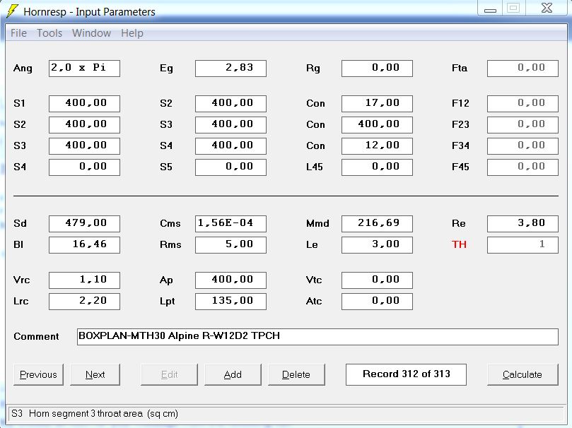
So I did some home work and came up with some input parameters for Hornresp exported from your magnificent MTH30.
Using the MTH30 workbook I entered external dimensions equivalent to the Lab12 Snyder and let the Optimise routine do its work.
I imported this into Hornresp and got the following input screen......
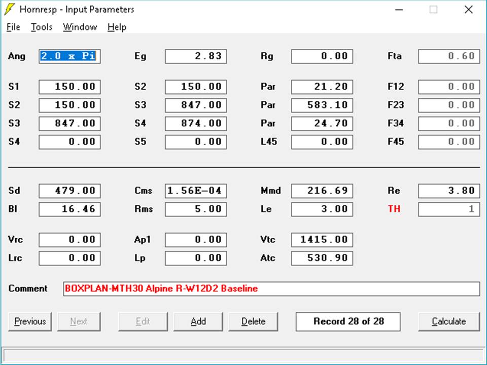
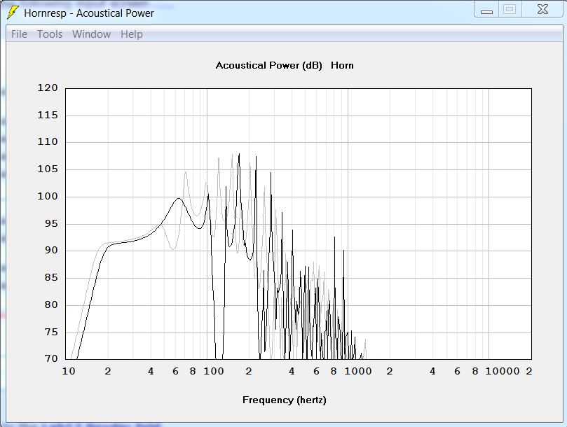
Here is how this MTH30 fold compares to the Lab12 Snyder fold.....
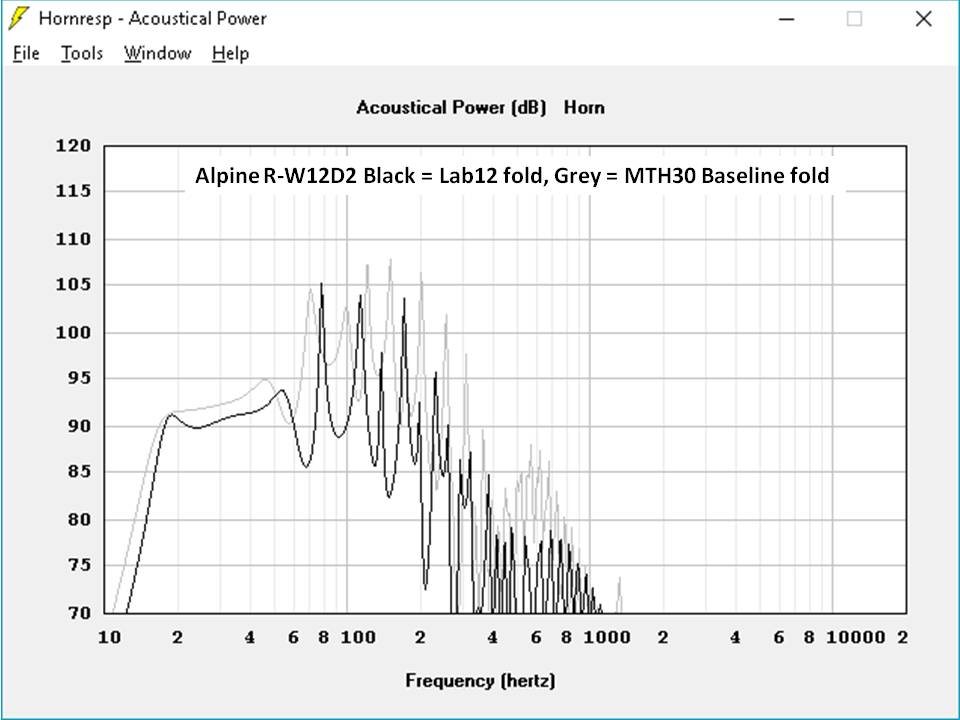
I think I like the MTH30 fold better. It goes just as low and looks smoother overall. That first big suckout around 60 hz is 5db less severe as are the rest up to approximately 100hz.
Am I missing anything here?
Thanks again!
Hi Brian,
So I did some home work and came up with some input parameters for Hornresp exported from your magnificent MTH30.
Using the MTH30 workbook I entered external dimensions equivalent to the Lab12 Snyder and let the Optimise routine do its work.
I imported this into Hornresp and got the following input screen......
Here is how this MTH30 fold compares to the Lab12 Snyder fold.....
I think I like the MTH30 fold better. It goes just as low and looks smoother overall. That first big suckout around 60 hz is 5db less severe as are the rest up to approximately 100hz.
Am I missing anything here?
Thanks again!
Attachments
If you add a front pipe section to a simple tapped pipe you can get a much larger usable passband. You get the same distortion nulling effect as Brian Steel mentions above.
Here compared with your "baseline" simulation above.
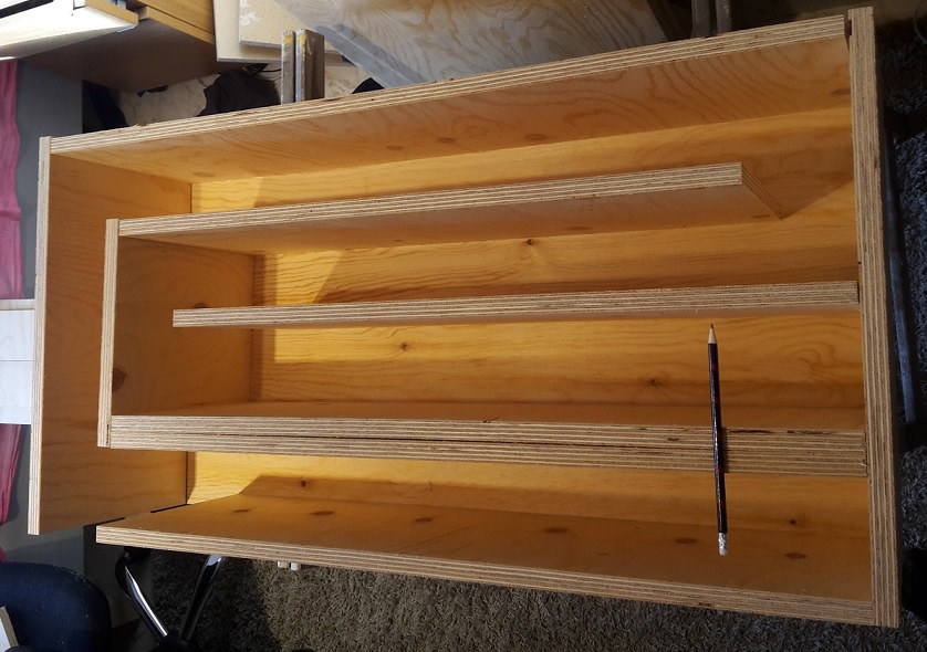
The driver should be under the pencil in the picture.
This is just an example to show a simple to build layout.
I've built and measured both a TP with a deep notch and a TH with a somewhat deep notch, both just above the passband. I prefer how they sound with the notch addressed, either through stuffing (in the case of the TH), or a precisely-located constriction (in the case of the TH)
@Brian Steele:
You did not seem to like the deep notch a few years back when I mention the same distortion lowering effect of a deep suckout above the passband.
Danley BC-subs reverse engineered
The driver should be under the pencil in the picture.
This is just an example to show a simple to build layout.
😱 what is this sacrilege? This is not tapped, it's a TL on both sides.
This is not tapped, it's a TL on both sides
Since both resonators share the same mouth I would call it a tapped pipe (with an added front resonator).
Since both resonators share the same mouth I would call it a tapped pipe (with an added front resonator).
I think the "tapped" configuration is only when the rear line comes past the driver again prior to exit, this is not the case here.
Since both resonators share the same mouth they will couple to each other.
The front resonator pipe section exits where the driver normally would tap into the pipe. The front resonator does not shield the driver in any way.
Why would this not be a tapped pipe?
The front resonator pipe section exits where the driver normally would tap into the pipe. The front resonator does not shield the driver in any way.
Why would this not be a tapped pipe?
Last edited:
- Home
- Loudspeakers
- Subwoofers
- Collaborative Tapped horn project