Hello Apex
greetings made the AX12C series bulb is glowing dim how to adjust the bias
warm regards
Andrew
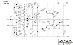
This pcb work in class B, something is wrong, remove output transistors and do some voltage measurements.
Hello Apexaudio,
Please post AX12c darlington transistor Schematic diagram.
Warm regards
Vedmitra Sharma
Please post AX12c darlington transistor Schematic diagram.
Warm regards
Vedmitra Sharma
Last edited:
Hello Apexaudio,
Please post AX12c darlington transistor Schematic diagram.
Warm regards
Vedmitra Sharma
Attachments
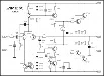
how should i adjust AX14's 1K Pot?which part voltage or current should i adjust?
Set 10mV voltage on 0R33 5W resistors for 30mA bias.
THANK YOU APEX
If amp oscilate add 100pF from base to colector TIP142,TIP47.
hi
a build AX14 amplifire but i have a problem
i series two 100ohm 3 watt resistor with positive an negative input voltage rail(+-45) for biasing and protect circuit from high current drain.
but when bias pot is above about 150 ohm voltage on 100 ohm series resistor is 0.8 volt and 2sc5200 Vbe is .2 and is off
but when pot is under about 150 ohm voltage on series 100 ohm resistor is 6 volts and 2sc5200 Vbe is 0.6 and is off but 100 ohm resistor voltage increase rapidly to about 40 volts!and become very hot
how should i bias my circuit?
i bias my circuit and set the 0.33 resistor voltage on 15mv but this voltage isn't stable and begin to raise.and 2sc5200 and 2sa1943 become warm and warmer.
2sa1943 and 2sc5200's Vbe is about 0.6
2sa1943's Vce is about 52 volts
2sc5200's Vce is about 27 volts
there is about 12 volts DC in output!
2sa1943 and 2sc5200's Vbe is about 0.6
2sa1943's Vce is about 52 volts
2sc5200's Vce is about 27 volts
there is about 12 volts DC in output!
Last edited:
hi apexaudio
i connect psu GND to input signal GND and circuit become biased and Vce on both 5200/1943 is equal now.
but according to AX14 schematic and wireing diagram when we connect psu gnd to siganal gnd C13 and 10 Ohm resistor are short circuit!
why did you put them in schematic?
https://www.diyaudio.com/forums/att...mate-fidelity-amplifier-apex-ax14-wireing-jpg
https://www.diyaudio.com/forums/att...w-ultimate-fidelity-amplifier-apex-ax17v2-jpg
- Home
- Amplifiers
- Solid State
- 100W Ultimate Fidelity Amplifier