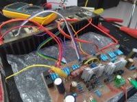
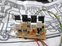
my investigation with sick chanell A40 continue.. so, i found microscopic interruption and this cond wasn´t connected.. when i mesure it and make pressure it was then wasn´t... very strange eror... so i think this is it... i have to wait for my new scope to confirm it... do you think tha could be this ?
Attachments

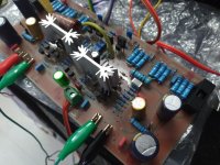
resistor above that 220uF should be 470kOhm,not 470 Ohm. also,at input should be 470 Ohm instead 100 Ohm and 470pF instead 100pF. you have put shot-wire instead of one capacitor? AlexMM had used two 470uF instead one 220uF,so one connection should be short-wired and 220uF capacitor should be mounted in such a way that his minus is connected to GND at pcb. on my pcb i used left capacitor place to make short-wire and right side capacitor to put 220uF with its minus placed to look at simetry trim-pot,and plus faced to input capacitor.
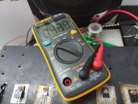
picture shows output signal?
(use this schematic: )
picture shows output signal?
(use this schematic: )
Attachments

Last edited:
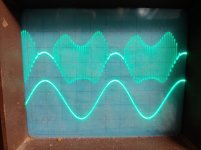
Yes. I have this values... Two 470u in series but one was not connected. Picture shows output before i found this eror.
Apex A40 build Success!! Thank you Mile!
Hi friends,
I am excited to share my Apex A40 success story with you🙂. Being my very first discrete project, I am really lucky enough to get a positive result.
Thanks and Salute to Mile for his wonderful diy friendly CFA. Thanks Alex for the error free layout. Thanks Prasi and Bhushan for your inputs. Also a big thanks to Sumesh, for being a ring away and building my confidence 🙂 .
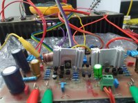
FORGIVE ME FOR THE DIRTY BUILD. I shall move the drivers and outputs to a proper heat sink soon.
As of now I have just connected a single pair of outputs with 30-0-30V AC x 2 trafo.
Below are the readings
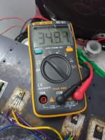
DC Offset: <10mV
Bias: 35mA for a single pair(voltage measured across the 10 Ohm resistor connected in series with the rail shows 350mV).
One question regarding bias, what should be the ideal bias per output pair?.
Also, I have the stability cap 22pf connected across the collector-base of the drivers. Amp is working fine without those caps as well. Should I keep those caps there in, or to remove ?
I would be using 2 pairs of outputs with 39-0-30 Volt AC, 5Amps per channel. is that fine?
Audio Impression: Clean flat sound from my car speakers. Mid is very clear and open, love it. Waiting for good drivers to test it properly.
Once again Thank to everyone who have helped me directly or indirectly 🙂
Regards,
Sha
Hi friends,
I am excited to share my Apex A40 success story with you🙂. Being my very first discrete project, I am really lucky enough to get a positive result.
Thanks and Salute to Mile for his wonderful diy friendly CFA. Thanks Alex for the error free layout. Thanks Prasi and Bhushan for your inputs. Also a big thanks to Sumesh, for being a ring away and building my confidence 🙂 .
FORGIVE ME FOR THE DIRTY BUILD. I shall move the drivers and outputs to a proper heat sink soon.
As of now I have just connected a single pair of outputs with 30-0-30V AC x 2 trafo.
Below are the readings
DC Offset: <10mV
Bias: 35mA for a single pair(voltage measured across the 10 Ohm resistor connected in series with the rail shows 350mV).
One question regarding bias, what should be the ideal bias per output pair?.
Also, I have the stability cap 22pf connected across the collector-base of the drivers. Amp is working fine without those caps as well. Should I keep those caps there in, or to remove ?
I would be using 2 pairs of outputs with 39-0-30 Volt AC, 5Amps per channel. is that fine?
Audio Impression: Clean flat sound from my car speakers. Mid is very clear and open, love it. Waiting for good drivers to test it properly.
Once again Thank to everyone who have helped me directly or indirectly 🙂
Regards,
Sha
Attachments
-
 P_20190214_142224-min.jpg402.2 KB · Views: 297
 -
 P_20190214_141814-min.jpg775.2 KB · Views: 320
 -
 P_20190214_141802-min.jpg779 KB · Views: 276
 -
 P_20190214_141743-min.jpg701.3 KB · Views: 325
 -
 P_20190214_141749-min.jpg770 KB · Views: 950
 -
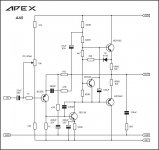
 APEX A40_latest by mile_instability 22pf added_ same is with A33.JPG625.5 KB · Views: 461
Hi friends,
I am excited to share my Apex A40 success story with you🙂. Being my very first discrete project, I am really lucky enough to get a positive result.
Thanks and Salute to Mile for his wonderful diy friendly CFA. Thanks Alex for the error free layout. Thanks Prasi and Bhushan for your inputs. Also a big thanks to Sumesh, for being a ring away and building my confidence 🙂 .
FORGIVE ME FOR THE DIRTY BUILD. I shall move the drivers and outputs to a proper heat sink soon.
As of now I have just connected a single pair of outputs with 30-0-30V AC x 2 trafo.
Below are the readings
DC Offset: <10mV
Bias: 35mA for a single pair(voltage measured across the 10 Ohm resistor connected in series with the rail shows 350mV).
One question regarding bias, what should be the ideal bias per output pair?.
Also, I have the stability cap 22pf connected across the collector-base of the drivers. Amp is working fine without those caps as well. Should I keep those caps there in, or to remove ?
I would be using 2 pairs of outputs with 39-0-30 Volt AC, 5Amps per channel. is that fine?
Audio Impression: Clean flat sound from my car speakers. Mid is very clear and open, love it. Waiting for good drivers to test it properly.
Once again Thank to everyone who have helped me directly or indirectly 🙂
Regards,
Sha
Nice work, enjoy in best diy amplifier ever🙂
Regards
Thank you Mile 🙂 Excited!! Giving me the confidence to do more builds.
Could you please answer the below queries.
Bias: 35mA for a single pair(voltage measured across the 10 Ohm resistor connected in series with the rail shows 350mV).
What should be the ideal bias per output pair?.
Also, I have the stability cap 22pf connected across the collector-base of the drivers. Amp is working fine without those caps as well. Should I keep those caps there in, or to remove ?
I would be using 2 pairs of outputs with 39-0-30 Volt AC, 5 Amps per channel. is that fine?
Regards,
Sha
Thank you Mile 🙂 Excited!! Giving me the confidence to do more builds.
Could you please answer the below queries.
Bias: 35mA for a single pair(voltage measured across the 10 Ohm resistor connected in series with the rail shows 350mV).
What should be the ideal bias per output pair?.
Also, I have the stability cap 22pf connected across the collector-base of the drivers. Amp is working fine without those caps as well. Should I keep those caps there in, or to remove ?
I would be using 2 pairs of outputs with 39-0-30 Volt AC, 5 Amps per channel. is that fine?
Regards,
Sha
Bias 30-50mA for single pair is OK
Keep 22pF
2 pairs of outputs with 42-0-42 Volt AC, 5 Amps per channel. is OK
Regards
Bias 30-50mA for single pair is OK
Keep 22pF
2 pairs of outputs with 42-0-42 Volt AC, 5 Amps per channel. is OK
Regards
Thank you for the quick reply. Next target is Apex P30, that would be a nice combo for A40 🙂
Regards
Sha
Congrats...You are awsome....
Hi friends,
I am excited to share my Apex A40 success story with you🙂. Being my very first discrete project, I am really lucky enough to get a positive result.
Thanks and Salute to Mile for his wonderful diy friendly CFA. Thanks Alex for the error free layout. Thanks Prasi and Bhushan for your inputs. Also a big thanks to Sumesh, for being a ring away and building my confidence 🙂 .
FORGIVE ME FOR THE DIRTY BUILD. I shall move the drivers and outputs to a proper heat sink soon.
As of now I have just connected a single pair of outputs with 30-0-30V AC x 2 trafo.
Below are the readings
DC Offset: <10mV
Bias: 35mA for a single pair(voltage measured across the 10 Ohm resistor connected in series with the rail shows 350mV).
One question regarding bias, what should be the ideal bias per output pair?.
Also, I have the stability cap 22pf connected across the collector-base of the drivers. Amp is working fine without those caps as well. Should I keep those caps there in, or to remove ?
I would be using 2 pairs of outputs with 39-0-30 Volt AC, 5Amps per channel. is that fine?
Audio Impression: Clean flat sound from my car speakers. Mid is very clear and open, love it. Waiting for good drivers to test it properly.
Once again Thank to everyone who have helped me directly or indirectly 🙂
Regards,
Sha
hi
dear "apexaudio"
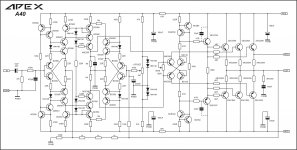
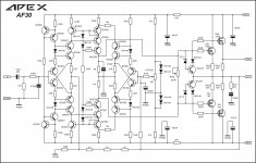
are these schematic and pcb an layout in post #320 final ones?
100W Ultimate Fidelity Amplifier
can i build that circuit without any problem or changes?
dear "apexaudio"
are these schematic and pcb an layout in post #320 final ones?
100W Ultimate Fidelity Amplifier
can i build that circuit without any problem or changes?
hi
dear "apexaudio"
are these schematic and pcb an layout in post #320 final ones?
100W Ultimate Fidelity Amplifier
can i build that circuit without any problem or changes?
Yes it is final AX14 schematic and pcb.
YouTube
Yes it is final AX14 schematic and pcb.
YouTube
why did you connect D4's cathode to 2SA1943's emitter?instead of connect it to output?

why did you connect D4's cathode to 2SA1943's emitter?instead of connect it to output?
It is the same only 0R33/5W resistor is in series with diode to the output.
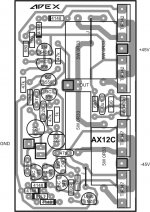
Hello Apex
greetings built AX12C but its drawing excess current how can bias be set series
bulb is glowing
warm regards
Andrew
greetings built AX12C but its drawing excess current how can bias be set series
bulb is glowing
warm regards
Andrew
Hello Apex
greetings built AX12C but its drawing excess current how can bias be set series
bulb is glowing
warm regards
Andrew
Use 1k trimpot instead 100R
- Home
- Amplifiers
- Solid State
- 100W Ultimate Fidelity Amplifier