Hello, can you send asc file, of course if this project is open source so I can play a little with simulations. Results do look very good 😀
When you simulate THD in class D, you put some dead time in the output section. And dead time is cause of major of distortion in class D.
When yo build real amplifier you see that THD you god in spice almost equals real THD you measures.
I wounder does this approach works for "non switching" amplifiers. I wonder if transistor models are good enough to simulate real "characteristics" of discrete elements like IRFP mosfets.. etc.
Full transfer / input / output characteristics given by model must equal real one from datasheet.
I do not say that simulation is not good, I just say that it may not be as accurate as for class D. (if simulation model dead time equals real amplifier dead time)
When you simulate THD in class D, you put some dead time in the output section. And dead time is cause of major of distortion in class D. When yo build real amplifier you see that THD you god in spice almost equals real THD you measures.
I wounder does this approach works for "non switching" amplifiers. I wonder if transistor models are good enough to simulate real "characteristics" of discrete elements like IRFP mosfets.. etc.
Full transfer / input / output characteristics given by model must equal real one from datasheet.
I do not say that simulation is not good, I just say that it may not be as accurate as for class D. (if simulation model dead time equals real amplifier dead time)
I have deadtime into the class d yes, for multilevel and smaller transistors however it can be very small.
here is a asc from the circlotron.
regards
Attachments
Hi Kees, I tried to make simulation using this "asc" file schematics.
Results with 0,0001 % THD are only when small output signal is below 10% of Vcc.
When about 50% of Vcc THD is about 0,06%. - 0,1 %
Maybe some parts in this amp are close to clipping (or non linear region), because THD rise starts very soon, pretty much far from output section clipping.
I wonder this part of this amplifier is causes most of non - linearities ? Maybe local feedback can be used to improve total THD at higher range if signal swing ?
When you make FFT graph, which "window" do you use (FFT setup) ?
Last edited:
Hi
What amp you do referring on?
There is a circlotron who has autobias and this is not yet usable becasue need more work, like real time because simulation get very long time.
I have used FFT window blackman harris and 5 points.
The nonliniarities can be caused because of gate capacitances of mosfets. the feedback is a current version, making voltage feedback is more difficult because of single input and balanced output.
I like current feedback much more.
regards
This one🙂circlotron ready, very nice-vertical-autobias1.asc (20.8 KB, 21 views)
Aha you say autobias does not work fine., maybe that is the problem.. steady state required long time simulation.
But why using autobias if in real amplifier just potentiometer can be used to set up bias ?!
Last edited:
Autobias is very good for keep the mosfets in idle all time.
This however need more sim time, you can disconnect the output to the current source and us a dc source there, adjust the voltage fpr proper bias.
The vertical mosfets also need when not use a autobias a servo, I did one who work on the thread.
This however need more sim time, you can disconnect the output to the current source and us a dc source there, adjust the voltage fpr proper bias.
The vertical mosfets also need when not use a autobias a servo, I did one who work on the thread.
I take back this claim... something went wrong in setup...
Idle current below 1 Amp also produce low THD...
Idle current below 1 Amp also produce low THD...
It is a little a game to simulate and see what happens with idle current.
yes you did right voltage source do replace the autobias, these is when simulating very slow, becais eof very long times as with a servo.
You do now that this idle setup with cause temperature runout?, putting the current source mosfets on heatsink do not work, it get the wrong way.
regards
yes you did right voltage source do replace the autobias, these is when simulating very slow, becais eof very long times as with a servo.
You do now that this idle setup with cause temperature runout?, putting the current source mosfets on heatsink do not work, it get the wrong way.
regards
But why, ? mosfets have kind of lower drain current with increase of temperature and constant gate voltage!?
Why not measuring voltage drop using op amp on source resistors of IRFP240? using that info to control the voltage and V7...
In real life how can we be sure that top part of output mosfets is identical to botttom part, so that output current is zero through 8 ohm speak. I presume DC servo serves to make it zero. This is useless in spice because all mosfets are identical, but source resistors may be changed to see if DC servo bias works.
But resistors at the output of DC servo bias seems to be too large R63 R27 R20. I think mosfet imbalance can be higher in reality... maybe lower value of those resistors should be used..
I am simulating and it seems that 6,5 V DC (at voltage source I put on schematics before) is optimal voltage for lowest THD..
0,0012% for 0,5Vin ( 27.5 V out peak)
0,0037% for 1 Vin (55V out, near clipping)
0,0025% for 0,25Vin (13 Vp out)
0,0013% for 0,1Vin (5,2 Vp out)
0,00038% for 0,05Vin ( 2,6 Vp out)
VERY good results !!!

The resistors on the servo output can not so low, for dissipation concerns however when use the amp for home and not big disco then it can be lowered to 100 ohms and 47 ohms. The servo left keeps the amp stable in the4 null volts on output for proper working of the autobias, but I did still have to test the other one who has only a servo who do both voltage and bias, see if that works, reason, the rectifier have not much work, the audio signals are already canceled out the servo did take care of the last stuff.
No not interested in such topologie, it is not needed, these just eat extra parts.
There is so much I need choose something time is limited here.
regards
There is so much I need choose something time is limited here.
regards
I actually agree..
All in all circotron works very nice in spice. What owuld making real model reveal ?
I suggest to remove all opamps, and maybe even use generic mosfets, to make simulation faster... Then we simulate different mosfet characteristics (so that DC servo has really to work to get zero V).. Up to know did you managed to create this amplifier in real life?
The real way to get a answer, is to build it, I do go start soon but now busy with the house, it needs work to get clean room and new stuff on the walls.
simulating is difficult, the autobias has a very long rc time it do impact distortion when put that to low, just try using a 100 n cap and not 1 uf.
the integrator of the autobias does need 4.7 uF or even higher, the dc servo needs to be sligtly faster to get it lock properly.
regards
simulating is difficult, the autobias has a very long rc time it do impact distortion when put that to low, just try using a 100 n cap and not 1 uf.
the integrator of the autobias does need 4.7 uF or even higher, the dc servo needs to be sligtly faster to get it lock properly.
regards
hi kees52,
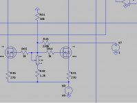
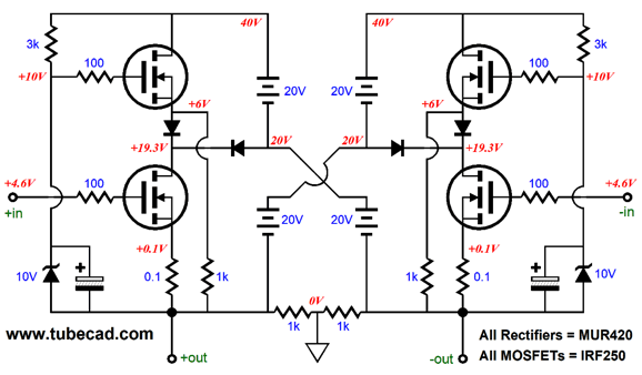
do you know how to simulate a wingspread with a circlotron output stage ?
simple push :
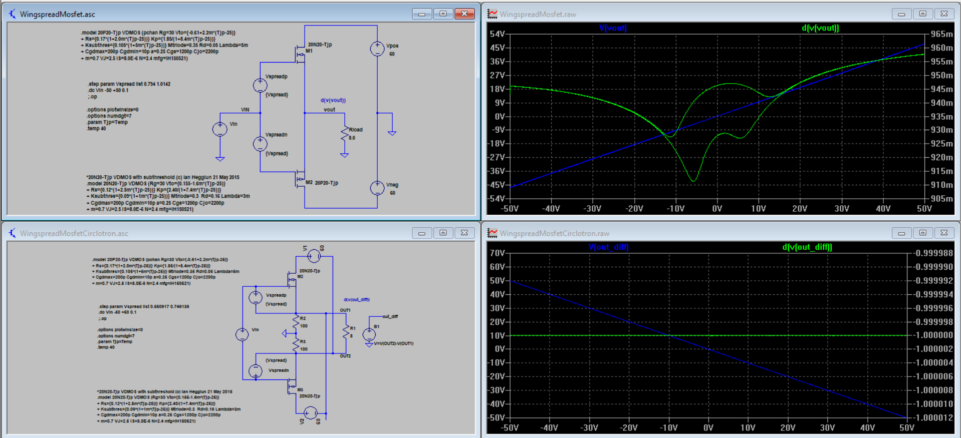
http://circlotron.audio/data/simulation/img/wingspreadMosfet.png
http://circlotron.audio/data/simulation/asc/WingspreadMosfet.asc
circlotron :
http://circlotron.audio/data/simulation/img/wingspreadMosfetCirclotron.png
http://circlotron.audio/data/simulation/asc/WingspreadMosfetCirclotron.asc
there is an error somewhere.....
do you know how to simulate a wingspread with a circlotron output stage ?
simple push :
http://circlotron.audio/data/simulation/img/wingspreadMosfet.png
http://circlotron.audio/data/simulation/asc/WingspreadMosfet.asc
circlotron :
http://circlotron.audio/data/simulation/img/wingspreadMosfetCirclotron.png
http://circlotron.audio/data/simulation/asc/WingspreadMosfetCirclotron.asc
there is an error somewhere.....
Hi
I do not now how to do that, I have not that much LTspice stuff learned, it is a scientific program and need much learning if you want do much, but you can ask on LTspice thread where professionals can give a answer, I do this also when not now.
Never heard of a bluhbaum system, what does it means? Is it a liniair way to let see a dc sweep?.
regards
Thorens TEM3200 use Blöhbaum System, it is just a circlotron 🙂

EP1548934B1 - Fully differential push-pull amplifier
- Google Patents
6moons audio reviews: Thorens TEM 3200
EP1548934B1 - Fully differential push-pull amplifier
- Google Patents
6moons audio reviews: Thorens TEM 3200
Last edited:
- Home
- Amplifiers
- Solid State
- allFET circlotron