Knowing the headroom you may clip at the input not clipping amplifier itself. Is it production type design? Especially if this does not damage amp.
Cheers
Cheers
Knowing the headroom you may clip at the input not clipping amplifier itself. Is it production type design? Especially if this does not damage amp.
Cheers
It is the output who does clip, and as a result the feedback does try error correction, so VAS is also distorted.
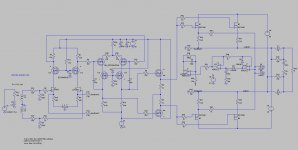
I have not very much open loop, however I use two cascodes, who does the job well. I do however ask myself of this is a good idea to drive the mosftes gate capacitance because cascodes are high impedance who needs a soruce follower, I have that as extra into the circlotron itselfs as a IRF 610, but means twice the voltage before idle gets up.
also the drive needs higher output, but the bridge do put that in half.
I see that the autobias needs always a sudden idle current, when not the system does not start because reference voltage stays higher.
So I'm look at a way to get it right, it is possible to start with 1 amp idle, everything above the idle I want is oke, so when I do 500 ma amp needs to start with 600ma as a example, or invert things but I do not now if that works.
I have no plans for commercialize this design, I do think about class D design, it is better and better with the new parts. and I have some done.
regards
Attachments
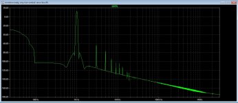
I have a question what proberly already is answered by alex, I get high distortion in the long tail pair or differential input stage, and very low at the output, but this can mean sound will be not that good, I presume there are here amp designers who can tell me if this is maybe because of current feedback, a current source below the input stage can help however current feedback then give for shure errors.
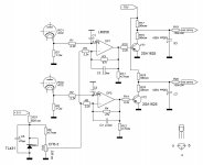
twh pics one the output probe and one the input stage who has jfets and cascoded with a mosfet.
thanks for help.
twh pics one the output probe and one the input stage who has jfets and cascoded with a mosfet.
thanks for help.
Attachments

Because I had offset problems what did disturb the autobias, I did this.
I have now two sides who balances such that with change off idle the offset stays put, now the autobias can regulate.
The schematic has move the mosfet source follower who drive powerfest to the driver secton plus voltage, so it dos not shift with the circlotron who do float.
now test it and distortion is quite low and this with vertical mosfets.
regards
Attachments

hold on Kees!
Madam is operated, and the tumor removed, ze had the luck there where not any metastases.
But danger is not yet over, now wait if it stays away, but signals are very good.
regards
Alex
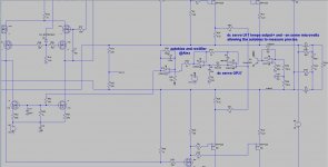
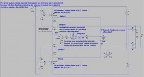
I have change things in the schematic, because we need zero volts on both out of fase outputs, I have included a dc servo, it give a negative error voltage nulling these outputs nicely, now I can let lock the autobias a lot better, both do work together nicely also, afcourse I do need a real live setup.
I have the AD843 into ltspice however it does not work properly, need a new model, I need a fast settling high bandwidth opamp with high input impedance for the rectifier.
What I did see it takes more then 2 seconds to settle with the caps used into your design, I have also set the dc servo high time constant, what is need here special not to influence audio signal.
Attachments
Listen, I personally do not use op/amp models per say in simulation(s). DIFF with gain and feedback will do. Secondly it was a mere exercise do see whether or not it's possible to do it. I you need more realistic model you may introduce pole into the aforementioned "model". You may check what the manufacturer puts into model. You will be surprised. Make "ideal" diode using any op/amp and add bleeding resistor/current drain.
Surely enough time constant should be quite large.
Cheers
Surely enough time constant should be quite large.
Cheers
Listen, I personally do not use op/amp models per say in simulation(s). DIFF with gain and feedback will do. Secondly it was a mere exercise do see whether or not it's possible to do it. I you need more realistic model you may introduce pole into the aforementioned "model". You may check what the manufacturer puts into model. You will be surprised. Make "ideal" diode using any op/amp and add bleeding resistor/current drain.
Surely enough time constant should be quite large.
Cheers
I can use also universal opamps, these are much faster. I am not such a hero with spice, so much possible.
I go build and test, much more fun.
But for shure, the dc servo do fine, have just some uV's on outputs.
If I like you did use two resistors between output the audio get canceled, therefore I can speed up the dc servo without any impact on audio.
Then it will be faster getting zero volts before the autobias kick in, hmm, let's try.
Then it will be faster getting zero volts before the autobias kick in, hmm, let's try.
Alex
I have discover that the DC servo alone also do keep bias constant, I do ask myself also why there is a need of a rectifier because the signal on both source resistors are canceled, with the dc servo it is for sure compleet suppressed, there is nothing to rectify.
Because the servo do try to keep his inputs on 1 uV or what opamp can do because his own offset, it does take also bias, a cirlotron do react also on bias if the reference resistors be drive so it give zero volts on both outputs.
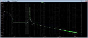
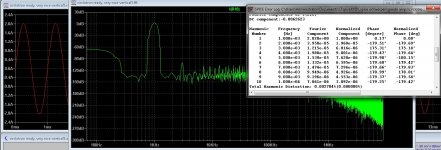
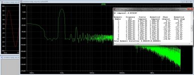
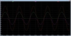
The picture shows what happens when I do disconnect on side of the circlotron, it lost bias current on the positive side of the signal, the negative goes fine, it keeps all the bias, and I have did big output current of 8 amps on 8 ohm.
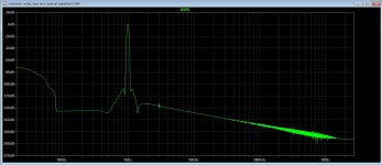
But as say the disbalans of the differential driver does give much more distortion. see pic three.
Nice playing, learning things.
With tubes she do it this way see pic two, looks nice if you do tubes.
I have discover that the DC servo alone also do keep bias constant, I do ask myself also why there is a need of a rectifier because the signal on both source resistors are canceled, with the dc servo it is for sure compleet suppressed, there is nothing to rectify.
Because the servo do try to keep his inputs on 1 uV or what opamp can do because his own offset, it does take also bias, a cirlotron do react also on bias if the reference resistors be drive so it give zero volts on both outputs.
The picture shows what happens when I do disconnect on side of the circlotron, it lost bias current on the positive side of the signal, the negative goes fine, it keeps all the bias, and I have did big output current of 8 amps on 8 ohm.
But as say the disbalans of the differential driver does give much more distortion. see pic three.
Nice playing, learning things.
With tubes she do it this way see pic two, looks nice if you do tubes.
Attachments
Alex I'm sorry.
I need some correction about the dc servo, it does job fine but do not correct for thermal runaway, reason is I did not include the source resistors.
What I have done now, special to keep it simple is include the source resistors, whereby the dc servo do keep o volts on in source of mosfets and the resistor voltage on output rails, because it does keep always 0 volts on mosfets, it measure also the idle, I can just change the current with a pot on vas, and it change current because voltage change also with it, dc servo does regulate it again to 0 volts having a different idle, it works I think I go do test it in real live now, soldering iron is on.
If I do set low time constant it does even not infloance sound, the servo is between the ground reference resistors, who cancel out the audio signals, because the servo does it's job it is perfect balanced, the same for the sense resistors, also there audio is canceled, thus no need for a rectifier.
Comment is always welcome.
regards
Attachments
Dear kees52. It looks like "If you said A you have to say B". The extraction circuit looks the way it does due to simulation and analysis of the voltages within the circuit. There is a reason why the biasing was done the way it was shown: as a passive adder with capacitors for AC to bypass.
It would not be wise to float PSU in respect to ground. I'll see waht can be done, however if the whole purpose is to simulate circuit using XXpice building nothing it's my very last post in this thread.
Cheers
It would not be wise to float PSU in respect to ground. I'll see waht can be done, however if the whole purpose is to simulate circuit using XXpice building nothing it's my very last post in this thread.
Cheers
Add a bleeder to peak detector cap. The results are attached. You may get secondary thermal distortions due to autobias being too fast. Whether or not you can filter it out enough to prevent distortions and still catch runaway I do not know. Make a thermal model and explore it. It does work the very same way with diode/transistor attached to the heatsink.
High order filters to the rescue!
High order filters to the rescue!
Attachments

Last edited:
Hi Alex
I go build, I have already that part done on a heatsink.
Yes I go make time constant big, because of faster sim I did make it faster.
to go to A or B, i like to experiment into sim, see what happens, What you mean by floating supply? maybe the regulator transistor as if these are not yet draw current thing is indeed compleet floating, but a resistor over these transistor helps a lot.
The reason I did go to B, I did discover a sideeffect of the dc servo, what you see in previous post, idle current and voltage on output rails is closely related, and as such, I can maybe use a servo alone with a big time constant, as you did mention.
real live is the best way, because if I did see possible it do not work, loos track later on drive amp to 80 amps, and blow stuff. that bleeder resistor of 1Meg I was forgotten, in mine hybride in mine home, who play now for 12 years has also a dc servo, but not a bleeder resistor, did work good and still does, so is this always needed or independent of what kind of opamp?.
Simulating temp, I think also here just building and testing, I have ordered the ad243 ic's already, I have not these here.
thanks for support, I appreciate that very much.
Af the floating supply, I do see now, a mistake, it flows through the minus 15 volts, need a parallel resistor over the transistor.
This way of doing it, there is no audio present, canceled, and only current ane dc offset, that was the idea about it all, that is why I ask about the rectifier, is that needed? when dc servo does balance it, then suppression of audio signals are maximal.
Post 952 I did set 1.6 volts on the reference resistors, that must bee -1.6 volts. for your autobias to work right, I can use a dc servo the normal way, together with your design, did that already and it does work nice, had set a mirror current source in the vas tail for signal, here I can maybe better use a opamp voltage to current for that, gets more complicated, interesting stuff, balanced amps are better suited for autobias? because of canceling effects.
Interesting it gets, I go heat up the iron.
regards
Last edited:
Alex
I have sim the version with the dc servo and the autobias.
For your design to work properly I need to nulling the two speaker outputs, normally not needed because she do cancel, but for autobias it needs really be stable, the dc servo does that, because integrators does startup quite chaotic need to have the servo a little faster then the autobias, but test wil let see whap happens.
I did try different and are soldering now the dc servo alone version who also take bias, to see if and what it does into the test setup.
The idle current of a circlotron does also let change the output voltages, it disturb the autobias action a lot. Now i hope it will not.
Need a input for the regulation signal of autobias, I did use now constant current mirror who is voltage controlled, need to think for best idea here.
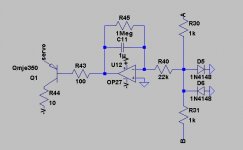
PS on pic you see very low offset voltages, I have use here a Op07 who dow well for that task, another thing about the capacitor bleeding resistor, when I do use it the offset rises to 29 mV instead of 0.3 uV without it. Maybe something to do that the op07 is a bjt opamp and no jfet.
And I have use fast times for integrator, this is only for the simulation, normally it has to be set beneeth 5 Hz.
regards
I have sim the version with the dc servo and the autobias.
For your design to work properly I need to nulling the two speaker outputs, normally not needed because she do cancel, but for autobias it needs really be stable, the dc servo does that, because integrators does startup quite chaotic need to have the servo a little faster then the autobias, but test wil let see whap happens.
I did try different and are soldering now the dc servo alone version who also take bias, to see if and what it does into the test setup.
The idle current of a circlotron does also let change the output voltages, it disturb the autobias action a lot. Now i hope it will not.
Need a input for the regulation signal of autobias, I did use now constant current mirror who is voltage controlled, need to think for best idea here.
PS on pic you see very low offset voltages, I have use here a Op07 who dow well for that task, another thing about the capacitor bleeding resistor, when I do use it the offset rises to 29 mV instead of 0.3 uV without it. Maybe something to do that the op07 is a bjt opamp and no jfet.
And I have use fast times for integrator, this is only for the simulation, normally it has to be set beneeth 5 Hz.
regards
Attachments
Last edited:
Did last things before I go on with the build, I have the powerstage soldered, en go put first the servo in to look at drift with temperature, and later on the autobias also in combination.
Because the circlotron do react also on bias when nulling th outputs maybe only a dc servo do control both, building is the best way to learn here.
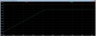
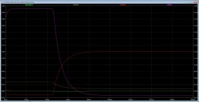
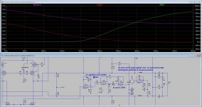
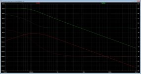
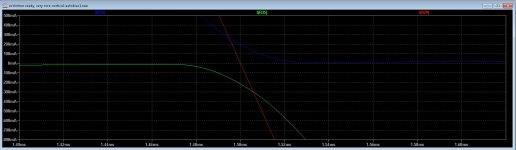
I have some extra sims, like the rc time and -3dB low pass who is 0.2 hertz and the fase of the servo autobias and amp 0-100Khz output.
Last plot is fase output from 0 to 100 Khz.
regards
Because the circlotron do react also on bias when nulling th outputs maybe only a dc servo do control both, building is the best way to learn here.
I have some extra sims, like the rc time and -3dB low pass who is 0.2 hertz and the fase of the servo autobias and amp 0-100Khz output.
Last plot is fase output from 0 to 100 Khz.
regards
Attachments
-
 ScreenHunter_1730 Dec. 18 19.08.jpg268.9 KB · Views: 173
 -
 ScreenHunter_1748 Dec. 20 14.47.jpg169.5 KB · Views: 173
 -
 ScreenHunter_1747 Dec. 20 14.43.jpg286.5 KB · Views: 89
 -
 ScreenHunter_1745 Dec. 19 21.03.jpg141.2 KB · Views: 81
 -
 ScreenHunter_1744 Dec. 19 21.01.jpg163 KB · Views: 100
 -
 ScreenHunter_1743 Dec. 19 21.01.jpg244.4 KB · Views: 107
 -
 ScreenHunter_1757 Dec. 21 14.57.jpg213.9 KB · Views: 93
Last edited:

- Home
- Amplifiers
- Solid State
- allFET circlotron