Look, nobody tells you what to do. Neither did I. It was a mere suggestion not to call it CFB.
Secondly, there are reasons why CFB utilize BJT and not FET.
Thirdly, if you do not do worst case analysis on drift, offset, loop gain etc. you get false impressions on performance, DC included.
Stop ever changing topology and schematics, choose what you are comfortable with and able to design per se and do it.
Hi Alex
I have some idea that not onlyn you are right but also that the allfet is possible not the best way, because I was curious about it I see the capacitances do really push to bad.
I have try to get a input for the adjustment of the servo, it is very sensitive, also here it is the mosfet who do now well into preamp, stability get worse distortions who in bjt are much better.
In schematic the signal has to go to a voltage to current converter, it needs to regulate afcourse, but mosfets are quite sharp, when do some wrong I get easely a comparator.
I have more succes with class D, and also with hybrid, but the cancer case of friend plays a role.
Thanks for thinking with me, I have learn some with that, and it is much fun.
Have a nice weekend.
Attachments
Last edited:
This hybrid, I have done has the most beautifull sound, people who hear did conferm. Do not care the feedback network, it can be also without feedback.
It is a all plate follower, only the output mosfets are source followers, I have build it and listen, it was suprising sound.
the servo here do well, mosfets are lateral. But was or has some ideas about circlotron, when use that with not matched parts, problems arise quickly.
You are right about ground reference, I did change that and have now low voltages so I can use autobias, only need a input for the regulation signal, voltage driving current source or voltage source, dc servo is easy, but bias is different.
Idea was use a allfet, because of tubesound effect, well, that is not right, except maybe depletion versions.
regards
Attachments
Last edited:
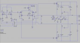
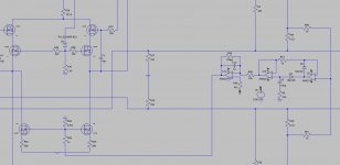
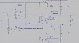
I have change the vas, now it has negative voltage also and current sources, distortion now did get very low, and now I can cancel out the dc voltages.
the two diodes on the measurement resistors do limt the voltage but I think it will block also regulation, so these are omitted for now, later on when back I go set it up furter.
trying without the 1 kohm resistors in circlotron output itselfs are needed, without them I get a power comparator, it just switch between supply rails when try to adjust, with them things are oke.
the two diodes on the measurement resistors do limt the voltage but I think it will block also regulation, so these are omitted for now, later on when back I go set it up furter.
trying without the 1 kohm resistors in circlotron output itselfs are needed, without them I get a power comparator, it just switch between supply rails
when try to adjust, with them things are oke.Attachments
Hi Kees!
I found something like this, I am not sure if it is EC or NSW circuit, maybe you will find it useful in your designs: http://forum.zelfbouwaudio.nl/downl...id=52bdb5d57235d5ea7f643bc47b2c42e3&mode=view forum: Circlotrom,pootje meer want anders - forum.zelfbouwaudio.nl
Hi Did miss you, your idea I can not use, I have a allfet, it is different.
I have done some sims this way, now to find out to let it lock on the right current, now it does not, little tricky, I have use voltage to current with two mosfets on the low side.
Sim is slow, because of integrator time settings, but maybe I can setup ltspice for that so I can see it right away.
regards
Sim is slow, because of integrator time settings, but maybe I can setup ltspice for that so I can see it right away.
regards
Attachments
I did again set a negative voltage for the current sources, so driver has a split supply on vas, it has big distortion without it because it did clip against the ground.
Now it can swing two sides, mucho better.
I do now try to let the autobias work, by making a input for that to the vas..
A plot of the opamps bias circuit does work, now to find proper way to let it lock. But with such big time constants I get long sim, maybe I can tell ltspice to speed that up.
regards
Attachments
Last edited:
Look, nobody tells you what to do. Neither did I. It was a mere suggestion not to call it CFB.
Secondly, there are reasons why CFB utilize BJT and not FET.
Thirdly, if you do not do worst case analysis on drift, offset, loop gain etc. you get false impressions on performance, DC included.
Stop ever changing topology and schematics, choose what you are comfortable with and able to design per se and do it.
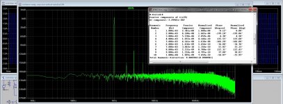
I have done a mc simulation, 60 times, and as expected the amp do cancel out errors, it stay stable, output is just some mV of drift not bad with a current feedback version.
This is due that both halves has same error what does cancel out dc on output.
regards
Attachments
Alex
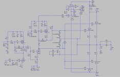
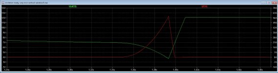
I have now set up that auto bias, however simulating that takes time because of the integrator capacitor, but what I see with smaller caps is that when drive hard, it do stay from zero in some extent meaning that it does seems to work.
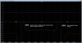
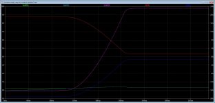
There are some difficulties of making the servo work, in this case I have included the voltage already present, and did setup the servo such that the amp starts with zero idle, otherwise it starts with 10 amps for couple hundreds of milliseconds.
This is what we want, keeping the idle current above zero so class B do never be reached. In the sim you see it go up after the integrator caps get charged and the reference and the rectifier signals get near.
You did use 10 uF in integrator, is that now really big? it will prevent that audio do have impact on idle. In this version I have a reference of dc voltage and the source resistors, so was 4.98 volts for 380mA I have setup the bjt so integrator opamp is between max regulating voltages.
regards
kees
I have now set up that auto bias, however simulating that takes time because of the integrator capacitor, but what I see with smaller caps is that when drive hard, it do stay from zero in some extent meaning that it does seems to work.
There are some difficulties of making the servo work, in this case I have included the voltage already present, and did setup the servo such that the amp starts with zero idle, otherwise it starts with 10 amps for couple hundreds of milliseconds.
This is what we want, keeping the idle current above zero so class B do never be reached. In the sim you see it go up after the integrator caps get charged and the reference and the rectifier signals get near.
You did use 10 uF in integrator, is that now really big? it will prevent that audio do have impact on idle. In this version I have a reference of dc voltage and the source resistors, so was 4.98 volts for 380mA I have setup the bjt so integrator opamp is between max regulating voltages.
regards
kees
Attachments
Last edited:
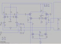
After some tests, it does work, calculation is precise as predicted when lock on the current, time constamt I had set not yet because of simulation time, when I do make the reference 0 volts it act as a dc servo, but then no current afcourse, also that did work.
I have use the mosfet current source of the vas, negative side, only when start, it does with high current, blowing fuse, so I have to start low, maybe invert the stuff can help, or a limiter who put only a max idle current when lock autobias is not yet done, maybe a zener can help here.
Did it with mucho thanks to Alexberg who have help me to learn how use that, thank you mine friend, now the tweeks because distortion is not that low, special on vas.
regards
now the rest.
Attachments
Is DC offset a problem? I ask that because there is no DC blocking capacitor is series with R10 feed back loop.
The dc offset will be multiplied by the ac gain off the amp withotu a capacitor down to ground.
I had a similar problem with an unstable amp. The cap was being reverse biased and becoming a short to DC.
The (circuit), actually the output stage, should not have bias at power up. It can be done either by keeping caps in timing discharged or you need to provide start up/shut down sequencing.
Last edited:
The (circuit), actually the output stage, should not have bias at power up. It can be done either by keeping caps in timing discharged or you need to provide start up/shut down sequencing.
Hi alex
I think it is due how the stuff start, when I can invert things then it starts ramping from zero current.
Alex, I have also try with that 5 volts + source resistor current, that do work also if I include voltage into the reference but think that is not so wise to do.
The zero voltage version do very well, starting high current, I go make a way to prevent, using cap or zener of such, making a max idle limit.
Or your design of autobias has to get inverted, and using upper voltage regulator to drive, now I do drive a current source on the lower side, ar maybe invert and then set reference voltage.
regards
The dc offset will be multiplied by the ac gain off the amp withotu a capacitor down to ground.
I had a similar problem with an unstable amp. The cap was being reverse biased and becoming a short to DC.
A circlotron do cancel out offset, when I get 3 volts on both halves i get zero on output, the beauty is that I can now use current feedback who is much beter audio quality then the normal feedback. A normal amp needs a servo for that.
Using caps into a current feedback path, I think do not work well, but we try all and learn.
thanks for answer Alex and nigelwrite.
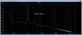
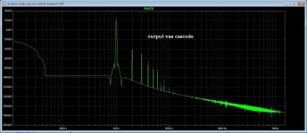
I have much more distortion if I R64 and R65 put to ground, that way i ahev no viltage anymore but just soms mv, that do work.
When I do set these resistor on higher value things get much better but amp get sensitive for idle current setup. I do be not shure about the cascode mosfet driver, is maybe the impedance much to high for mosfet drive? and is that also the reason that with low resistance I get more distortion, when probe the vas output it has much more distortion then the output, so canceling do work but do not mean a good sounding amp.
For the start with high current, I can put a extra resistor devider setup at 1 amp max limit, I need to start with some current or need to invert the autobias integrator bu it is difficult then to get a input somewhere.
Attachments

Hi All
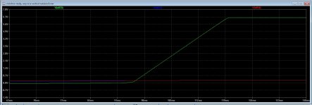
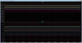
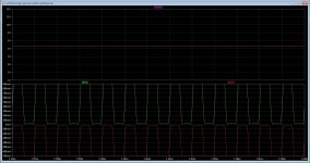
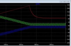
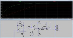
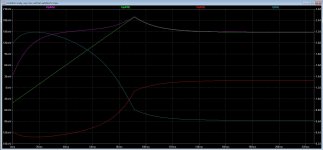
For Alex, your rectifier and integerator does work, however, I need to set the current higher then needed when start up, the ramping of the source resistor and the reference voltage do never reach each other when I do set low.
pic one is locked, and pic two it do never reach the reference voltage because of to low current on start.
However when invert the servo as whole, it is the opposite case, it always do ramping right, and as such the amp does start wihthout idle current.
Maybe last is mucht better.
Thanks and have a nice day.
Attachments
wel when let things clip, the autobias do trally not like that, but put bias never to zero, so it looks like it work wel. I do have to widening the integrator time constant because that give trouble when to small, need 1 hz or so.
now I go finetune, try some things. see if i can lower cascoded VAS distortion who I do not understand why
regards
now I go finetune, try some things. see if i can lower cascoded VAS distortion who I do not understand why
regards
Attachments
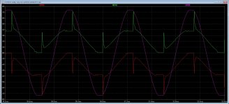

Why would anyone listen to clipping amplifier unless it's for Fender?
Fender has also not that kind of clipping, it is nasty.
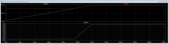
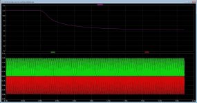
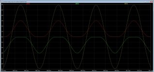
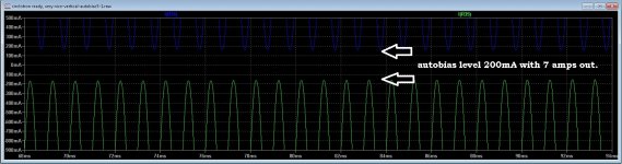
But I did let see that even with clip, the bias is still present, here is one without autobias, then it run out completely. I do see that part do hit zero but where singal goes through zero and crossover can occur there is still 800 mA or more bias, while I did set it up to around that value.
So this is how auto bias do work, in principle the amp stays in class a mode for some extent.
regards
Attachments
- Home
- Amplifiers
- Solid State
- allFET circlotron