I dont remember much I wrote or said in 2012. I would like to ask steven if he ever got around to build an amplifier of his own or others design. Cheers!
This is the usual misunderstanding about this output stage circuit that will come out again and again, forever again.Note: The two common collectors at each output would not introduce the typical nonlinearity because of the general feedback which will make the operational amplifier "switch" the transistors (go through zero) without a problem because the feedback is after the transistors and wil make the amplifier follow the shape of the voltage.
The feedback in this circuit DOES NOT work as you think.
This output stage is just terrible. It has a gross amount of distortion that makes it useless for HiFi audio. And there is no way to improve it.
This is the usual misunderstanding about this output stage circuit that will come out again and again, forever again.
The feedback in this circuit DOES NOT work as you think.
This output stage is just terrible. It has a gross amount of distortion that makes it useless for HiFi audio. And there is no way to improve it.
I think SSB should get an award for tenacity in defending this after 6 years to build it and see it do what everybody said it would. StevenStanleyBayes, you STILL persist in defending this mess? One should learn something in 6 years.
Happy New Year anyway and good luck to you.
G²
Unfortunatly very high slew rate will not fix the issue.
This is because the op amp bandwith comes in.
One can quickly see it with a Spice simulation. Or this can be proved with a correct modeling of what happens at cross over.
At crossover while the output of the op amp slews inside the BJTs bases gap, nothing happens at the BJTs output, so there is NO feedback. That means the op amp works OPEN LOOP, so it is terribly SLOW. For instance assume a typical 12 MHz 120dB op amp, it's 12MHz bandwith at gain 1 drops to 12 Hz when open loop at gain 1.000.000.
Yes 12 Hz, this is damn slow.
In this circuit with usual op amps, speed limiting comes from bandwith earlier than slew rate.
Note: The two common collectors at each output would not introduce the typical nonlinearity because of the general feedback which will make the operational amplifier "switch" the transistors (go through zero) without a problem because the feedback is after the transistors and wil make the amplifier follow the shape of the voltage.
The basic working of the feedback is indeed as you describe but the transition through the dead zone takes a finite time, and during this time the loop is broken while the opamp desperately tries to slew to the new output value.
This leads to unavoidable and large cross-over distortion.
You can try to minimize it with a very high slew rate opamp, or by using at least one diode in the bias to halve the transition region, but it will never go away.
Peter Walker got very far with the Current Dumping principle in the QUAD 405, but even he had to admit that it was limited and came out with the 405-2 where he put a diode in the bias circuit to cut the transition region in half. But xover is still clearly visible in the 405-2.
Jan
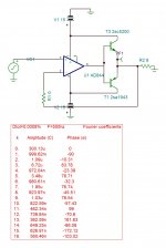
If 0.0008% at 1vp is not yet enough, what you think it should? See the spec of AD844. The open loop frequency is adjustable from 12khz and over by adding a resistor on TZ if necessary.
Last edited:
Yes, it will never go away........the transition through the dead zone takes a finite time, and during this time the loop is broken while the opamp desperately tries to slew to the new output value.
This leads to unavoidable and large cross-over distortion.
You can try to minimize it with a very high slew rate opamp, or by using at least one diode in the bias to halve the transition region, but it will never go away.
Jan
However slew rate is not what slows the crossing of the dead zone. The bandwith of the op amp is the culprit.
From simulations, I was amazed to see slower than expected considering the op amp slew rate figure, then I found that the op amp bandwith is what governs the duration of the dead zone crossing.
Then I proved with calculations that this duration was going inverse of the square root of the bandwith figure. In other words, to divide this duration by 10 would ask for an op amp with a x100 bandwith.
This is a lost race.
Last edited:
I do not agree with that, bandwidth is a small-signal parameter, slew rate is the large-signal parameter of interest here.
But the effect is the same, it takes time to slew through the dead zone.
Jan
But the effect is the same, it takes time to slew through the dead zone.
Jan
If 0.0008% at 1vp is not yet enough, what you think it should? See the spec of AD844. The open loop frequency is adjustable from 12kHz and over by adding a resistor on TZ if necessary.
Putting a resistor at Tz only makes the gain lower giving less feedback in the audio band, so that's not smart. The ol bandwidth is not of interest, what we need here is highest possible gain at high frequency where the slewing takes place.
The 0.0008% is misleading, because very narrow xover distortion at the zero crossing is very low when measured as THD but it consists of very high distortion pulses at zero crossing and can be very audible.
Jan
Last edited:
What’s with all the negativity? There’s MATHS used in the posts. Plus it’s universal. We need not use any other amplifiers, this one does it all.
Yes it takes time to cross the open loop zone . From -0.6 to +0.6 with 2000V/us it takes 0.6ns , if germanium ,0.2ns . For a PA amp it is excellent if it is used in QSC mode. The open loop frequency is determined by 3Mohm and 4.5pf , adding 3Mohm doubles the frequency response, yes it halves the gain . (best sound I get with this op amp for unity gain is with 1Mohm whereas DAC users go down to 1.5k with 1nf ).
I agree that the AD844 is a great candidate for this application. But those slew rate numbers are more subtle than they appear. You can only get it with a largish input signal. This input signal is the difference between Vin and the feedback signal which is a fraction of Vout. So immediately you see that high slew rate only happens when there is already distortion (difference between Vin and Vout). It is the higher-than-normal distortion at xover that drives the slewing of the opamp output.
A bit of biasing for lower slew rate requirements gives better linearity and lower peak xover distortion. Whether it is audible or not is another story of course.
Jan
A bit of biasing for lower slew rate requirements gives better linearity and lower peak xover distortion. Whether it is audible or not is another story of course.
Jan
Do a simulation, it is easy with LTSpice.
You will see: Results that do not agree with your calculations or explanations based on the op amp slew rate.
You will see: Results that do not agree with your calculations or explanations based on the op amp slew rate.
This was very long ago, lost into oblivion.
It doesn't take much time to put together: One op amp, two BJT, three resistors, two PSU voltages and a sine input.
All is available in LTSpice with a wide choice of op amps and bjts, and there is no need for fancy componants.
It doesn't take much time to put together: One op amp, two BJT, three resistors, two PSU voltages and a sine input.
All is available in LTSpice with a wide choice of op amps and bjts, and there is no need for fancy componants.
Last edited:
What I don't understand is the reason for creating a hole in the boat and then discussing the ways of plugging it, assuming it's pretty easy to avoid creating this hole in the first place.
Why don't the author bias the OPS properly?
THD doesn't mean too much by itself. Especially in a simulation. Distortion in the crossover region creates countless high order components, resulting in bad intermodulation.
Cheers,
Valery
Why don't the author bias the OPS properly?
If 0.0008% at 1vp is not yet enough, what you think it should? See the spec of AD844. The open loop frequency is adjustable from 12khz and over by adding a resistor on TZ if necessary.
THD doesn't mean too much by itself. Especially in a simulation. Distortion in the crossover region creates countless high order components, resulting in bad intermodulation.
Cheers,
Valery
What I mean is, that we use to talk about feedback as 'driving the input difference to zero' and that's a convenient rule of thumb but not really correct.
Any signal at the opamp output requires a difference in inputs (Vin and feedback) so by definition it can only work when there is distortion. That is also the reason that feedback can never drive the distortion to zero; distortion, however small, is required for the amp to work!
With an output stage in class B like here, it requires relatively high output levels from the opamp during slewing and thus requires a higher-than-normal distortion.
Whether all this is relevant for the level of performance you are after is up to you, but if you think hard about how feedback amps really work, you can't deny this.
Jan
Last edited:
What I don't understand is the reason for creating a hole in the boat and then discussing the ways of plugging it, assuming it's pretty easy to avoid creating this hole in the first place.
Why don't the author bias the OPS properly?
THD doesn't mean too much by itself. Especially in a simulation. Distortion in the crossover region creates countless high order components, resulting in bad intermodulation.
Cheers,
Valery
I gave the example of the 405-2 where Peter Walker decided to bias the output stage with a single diode to improve it. I have played with biasing with two schottky's or a 1N4148 + one schottky, still keeping the output stage in class B so no adjustment needed, but much, much lower xover distortion. Cost is trivial, result very worth while.
Jan
- Home
- Amplifiers
- Solid State
- Universal Audio Amplifier