The result is obtained by TI Tina simulator the models are from Toshiba for transistors and from AMD for ad844 . I fully agree , the distortion doesn't image the sound quality. This why I am concerned only with class A amps and nowadays , powered by FSS, Floating Single Supply . The bias circuit has always been the weak point of class B amps in terms of reliability. It is the nightmare for DIYs, if all will explode on first start up.
Last edited:
I think you mean nightmare for class A(B), where the bias needs to be adjusted and stabilized against temperature.
Class B is attractive for the absence of these issues. And with a little more circuit finesse to avoid hard class B, the performance can be very good indeed; no need to throw away the baby with the bathwater.
Jan
Class B is attractive for the absence of these issues. And with a little more circuit finesse to avoid hard class B, the performance can be very good indeed; no need to throw away the baby with the bathwater.
Jan
Just as a matter of interest
A quick simulation (I use Multisim).
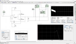
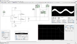
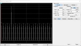
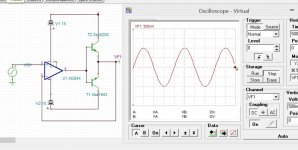
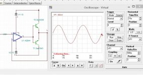
First of all, the circuit is unstable, showing an amplitude peak (and corresponding phase artifact at around 30MHz), mostly caused by the output pair's input capacitance. See 1 KHz and 20KHz simulations at the pictures 1 and 2. Note the crossover artifacts within the oscillation at 20KHz scope picture.
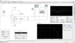
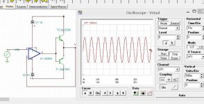
OK, not a big problem - we compensate with feed-forward RC according to AD844 datasheet - now amplitude and phase responses look good (pictures 3 and 5) and the system is unconditionally stable. But oscillation is not the biggest problem.
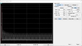
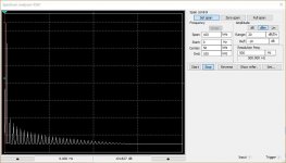
Pictures 4 and 6 show the spectrums at 1KHz and 20KHz. They don't look good - long "tails" of high-order components (pretty much as expected).
The simulations shown are performed at 1Vp. Level of distortion strongly depends on the signal level. At 100mV distortion will increase 10-20 times (influence of crossover distortion increases at the lower signal levels).
I agree with Jan - a couple of Schottky diodes between the bases will improve the situation, but the crossover distortion is not the only problem here - a proper driver stage is required for dealing with a high input capacitance of the output transistors, reducing distortion at the higher end of the audio frequency range.
Cheers,
Valery
A quick simulation (I use Multisim).
First of all, the circuit is unstable, showing an amplitude peak (and corresponding phase artifact at around 30MHz), mostly caused by the output pair's input capacitance. See 1 KHz and 20KHz simulations at the pictures 1 and 2. Note the crossover artifacts within the oscillation at 20KHz scope picture.
OK, not a big problem - we compensate with feed-forward RC according to AD844 datasheet - now amplitude and phase responses look good (pictures 3 and 5) and the system is unconditionally stable. But oscillation is not the biggest problem.
Pictures 4 and 6 show the spectrums at 1KHz and 20KHz. They don't look good - long "tails" of high-order components (pretty much as expected).
The simulations shown are performed at 1Vp. Level of distortion strongly depends on the signal level. At 100mV distortion will increase 10-20 times (influence of crossover distortion increases at the lower signal levels).
I agree with Jan - a couple of Schottky diodes between the bases will improve the situation, but the crossover distortion is not the only problem here - a proper driver stage is required for dealing with a high input capacitance of the output transistors, reducing distortion at the higher end of the audio frequency range.
Cheers,
Valery
Attachments

Last edited:
Nice Valery. Yes it was clear from the earlier posted schematic that it hadn't really be tested in any way.
For compensation I probably would have used a small 'base stopper' of 10 or 20 ohms, to isolate the base caps from the '844 output. But your way works fine.
Using darlingtons for the output devices would also help, after all at 15 supply and 8 ohms, output currents are manageable.
And some bias of course. Maybe you can try that as a quick see in your sim?
That would all make it a nice little amp to have around.
Edit: yes, the nature of the distortion really makes it a b*tch at low levels where we do most of our listening...
Jan
Last edited:
I agree, which is not politicaly correct on diyaudio........no need to throw away the baby with the bathwater.
Jan
The realities of thermal stability do not exist on diyaudio simply because simulators do not support thermal behavior. Until the built power amp blows up. Hopefully, there was time to listen ( or measure ? ) a best thd ( +n for a more professional look )
simply because simulators do not support thermal behavior.
I think you'd want to revise this statement in view of reality....
Jan
Nice Valery. Yes it was clear from the earlier posted schematic that it hadn't really be tested in any way.
For compensation I probably would have used a small 'base stopper' of 10 or 20 ohms, to isolate the base caps from the '844 output. But your way works fine.
Using darlingtons for the output devices would also help, after all at 15 supply and 8 ohms, output currents are manageable.
And some bias of course. Maybe you can try that as a quick see in your sim?
That would all make it a nice little amp to have around.
Edit: yes, the nature of the distortion really makes it a b*tch at low levels where we do most of our listening...
Jan
Here we go 🙂
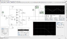
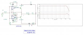
A slightly improved version of the same amplifier.
Simple driver stage, two pairs of diodes, setting the OPS bias close to the edge of class B (idle current of the output stage is around 0.5mA).
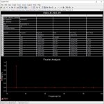
Much better performance. 2-nd picture shows the details of FFT, measuring THD (1KHz) = 0.00033%. THD (20KHz) = 0.003% (not shown here), which is still very good.
Look at the spectrum! Descending right side is what we were looking for 🙂
It also leads to much lower intermodulation, which is even more important for the better sound.
In fact, at this power level, some TO-220 transistors at the output would be enough. MJL15032/15033 is an example.
Cheers,
Valery
Attachments
With Tina I don't get oscillations. I'll try it in real next month in QSC mode.
Try feeding the input with 20KHz - in my simulation, it falls in oscillation right away if not compensated. My models are pretty good - AD844, NJW3281/1302, and 2sc5200/a1943 were live-tested, performing very close to simulations.
With Tina I don't get oscillations. I'll try it in real next month in QSC mode.
You have direct feedback, zero ohms. That may help stability. Not sure if the AD844 models input pin parasitic capacity.
BTW what's 'QSC mode'?
Jan
Here we go 🙂
A slightly improved version of the same amplifier.
Simple driver stage, two pairs of diodes, setting the OPS bias close to the edge of class B (idle current of the output stage is around 0.5mA).
Much better performance. 2-nd picture shows the details of FFT, measuring THD (1KHz) = 0.00033%. THD (20KHz) = 0.003% (not shown here), which is still very good.
Look at the spectrum! Descending right side is what we were looking for 🙂
It also leads to much lower intermodulation, which is even more important for the better sound.
In fact, at this power level, some TO-220 transistors at the output would be enough. MJL15032/15033 is an example.
Cheers,
Valery
Starts to look like a half-way decent amp ;-)
Jan
Cool. 🙂
Now use a LT6090 op amp to allow much higher output voltage, and replace the two 15K with two CCS to allow near rail to rail operation and good power supply ripple rejection.
LTC6090/LTC6090 -5 - 140V CMOS Rail-to-Rail Output
Now use a LT6090 op amp to allow much higher output voltage, and replace the two 15K with two CCS to allow near rail to rail operation and good power supply ripple rejection.
LTC6090/LTC6090 -5 - 140V CMOS Rail-to-Rail Output
Last edited:
Cool. 🙂
Now use a LT6090 op amp to allow much higher output voltage, and replace the two 15K with two CCS to allow near rail to rail operation and good power supply ripple rejection.
LTC6090/LTC6090 -5 - 140V CMOS Rail-to-Rail Output
Even better! Yes these are nice opamps. Not the fastest on the block but they may work OK here. There's anyway not much choice at higher supply voltages.
Jan
Here is 20khz and 100khz , at your service.
Why are the curves so low res? Anyway, sometimes it is instructive to scope the opamp output as well.
Jan
sorry my circuit is wrong . Indeed above 500hz oscillations occurs.
Yes, I see now - the power supplies are connected the wrong way.
But no problem - the compensation feed-forward RC makes the trick. Thanks to the access to internal buffer's input, provided by AD engineers 😉
If you can build the bode plot in your simulation - you will see the amplitude / phase response without compensation as well as having it in place.
love those ideal transistors with no Vbe bias required. Crossover distortion at 20khz and especially 100khz should be (very) Visible.
- Home
- Amplifiers
- Solid State
- Universal Audio Amplifier