About 50W QSC: Floating PSUs.
How are the 35v floating PSUs implemented ?
What parasitics are introduced by the floating PSU ?
Is it possible to use switched mode PSU ?
How are the 35v floating PSUs implemented ?
What parasitics are introduced by the floating PSU ?
Is it possible to use switched mode PSU ?
Last edited:
power supply
I advise you to use the FSS (Floating Single Supply) mode, See QSC1200, with SMPS. It requires low ESR capacitors of 4700uf -10000uf 50V. The SMPS has inner capacitor linking the output to earth about 1nf-5.7nf. This capacitor comes in parrallel with the speaker. If inboard isolated SMPS is used than the ground of the circuit is linked the earth via 2.2ohm to 10ohm resistor, which is very commonly used in high end components. Most SMPS have input EMI filter, if not external one unit for both channels may be necessary. A 6A sold on Ali as, EMI for DAC,cost less than 3$.
Some SMPS have soft start up, if not, the high capacitive load will not allow to start. A soft start circuit will be necessary, see CCPP amplifier. NEW class A :Constant Current Push Pull amplifier with single SMPS and hybrid preamp
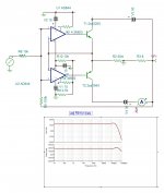
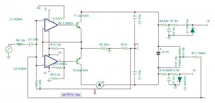
The quick designed circuit doesn't follow thermal variation. It can be done by either adding 0.22ohms emitter resistors and replacing R9 by NTC / voltage multiplier. Or R9 is replaced by voltage multiplier made of two BD 139 transistors mounted each upon the outputs ones, no emitter resistors.
I advise you to use the FSS (Floating Single Supply) mode, See QSC1200, with SMPS. It requires low ESR capacitors of 4700uf -10000uf 50V. The SMPS has inner capacitor linking the output to earth about 1nf-5.7nf. This capacitor comes in parrallel with the speaker. If inboard isolated SMPS is used than the ground of the circuit is linked the earth via 2.2ohm to 10ohm resistor, which is very commonly used in high end components. Most SMPS have input EMI filter, if not external one unit for both channels may be necessary. A 6A sold on Ali as, EMI for DAC,cost less than 3$.
Some SMPS have soft start up, if not, the high capacitive load will not allow to start. A soft start circuit will be necessary, see CCPP amplifier. NEW class A :Constant Current Push Pull amplifier with single SMPS and hybrid preamp
The quick designed circuit doesn't follow thermal variation. It can be done by either adding 0.22ohms emitter resistors and replacing R9 by NTC / voltage multiplier. Or R9 is replaced by voltage multiplier made of two BD 139 transistors mounted each upon the outputs ones, no emitter resistors.
Attachments
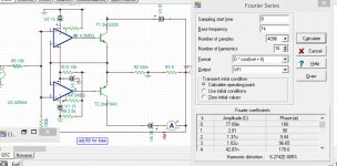
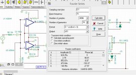
Designed in few minutes. Distortion measured at 10khz 0.01/50w 0.007%/1w.
As was pointed out here several times, the THD numbers in a class B design are largely useless. The very narrow xover distortion pulses translate to relatively low THD but they are very high in amplitude and generate a slew of higher harmonics.
Jan
The 'QSC' method is quite old, used in earlier times to allow driving the output stage with opamps at +/-15V supply. That is about the only advantage. Because the output stage runs in common emitter, the output impedance is intrinsically high and must be brought down by heavy feedback.
Edit: early Transnova amps used it too iirc.
Jan
Edit: early Transnova amps used it too iirc.
Jan
Refering to posts #160 ( and #162 ? ) What is QSC ? A brand ! A topology !
Is it Class B ( at Xover both BJTs are OFF )
or
can it be biased Class AB ( at Xover both BJTs are active )
Is it Class B ( at Xover both BJTs are OFF )
or
can it be biased Class AB ( at Xover both BJTs are active )
Last edited:
QSC is a brand name, a manufacturer name, used for marketing, nothing to do with a topology. QSC have used many different topologies, class (A)B, class D whatever, throughout the years.
If you want to give a name to the circuit presented here, it's a transconductance amplifier (voltage in current out) topology.
Jan
If you want to give a name to the circuit presented here, it's a transconductance amplifier (voltage in current out) topology.
Jan
Refering to posts #160 ( and #162 ? ) What is QSC ? A brand ! A topology !
Is it Class B ( at Xover both BJTs are OFF )
or
can it be biased Class AB ( at Xover both BJTs are active )
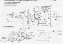
QSC is the brand, known for its robust professional stage amplifiers.
They utilize pretty much the same topology throughout a number of their product lines - opamp, followed by the OPS with grounded collectors and floating power supply (or 2 supplies).
Grounded collectors are pretty useful for professional applications - no insulation pads required, easy to service, etc.
However, what is good for a stage amplifier, is not good for a high-quality home audio system. Stage amplifiers and home audio amplifiers are designed with rather different requirements in mind. In a nutshell, home audio amplifiers are aimed to provide much higher sound quality at a much less stressed environment, than the stage amplifiers.
QSC is a brand name, a manufacturer name, used for marketing, nothing to do with a topology. QSC have used many different topologies, class (A)B, class D whatever, throughout the years.
If you want to give a name to the circuit presented here, it's a transconductance amplifier (voltage in current out) topology.
Jan
Jan, the one presented above is just an "inside out" follower arrangement - after more in-depth study, you can see that the output transistors' collectors are all tied together and grounded. The output node is driven by their emitters, although the floating supplies add some garbage anyway.
What we have in post #160 and #162 is not the topology of the original post.
I am not used to this topology, I was wondering about how it compares with the conventional way.
Thanks to Valery and Jan, I think I have the main answers.
Is there some hope for high quality of sound ?
I am not used to this topology, I was wondering about how it compares with the conventional way.
Thanks to Valery and Jan, I think I have the main answers.
Is there some hope for high quality of sound ?
Last edited:
Jan, the one presented above is just an "inside out" follower arrangement - after more in-depth study, you can see that the output transistors' collectors are all tied together and grounded. The output node is driven by their emitters, although the floating supplies add some garbage anyway.
Yes I see, I missed that top part. But it still is a transconductance amp, no?
Jan
As JAN mentioned Hafler transnova is also QSC type . If you consider QSCs are rough PA amps then read the review of Hafler's on
Hafler Transnova 9500 power amplifier Page 2 | Stereophile.com
Hafler Transnova 9500 power amplifier Page 2 | Stereophile.com
I wouldn't call it 'QSC type'. QSC is only one of several manufacturers who have (in the past) used this particular transconductance topology.
You wouldn't call all diesel cars 'Audi type' just because Audi uses diesel engines.
Jan
You wouldn't call all diesel cars 'Audi type' just because Audi uses diesel engines.
Jan
Yes I see, I missed that top part. But it still is a transconductance amp, no?
Jan
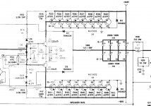
I agree it's still a transconductance amp, but QSC did a wise thing - its transconductance stage is buffered with the followers, driving the load with the low-Z emitters.
Hafler 9500 - similar transconductance arrangement, but it consists of the output FETs (lateral ones), driving the load with their drains. As you mentioned earlier - that's where they face the output impedance issue, addressed by simply a lot of feedback. They also miss the advantage of grounded collectors (or drains) for the output devices. Very simple though, plus those laterals don't need any temperature compensation. Dead simple 🙂
QSC design looks more sophisticated. The pro-grade approach is clearly visible.
Pictures for the reference:
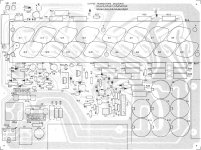
1) QSC 1700 OPS (temperature compensation is in place);
2) QSC 1700 Layout - the metal-case output devices all touch each other;
3) Hafler 9505 OPS.
Cheers,
Valery
Attachments


Last edited:
The first patent deposited of this circuit is in 1979 by Patrick H Quilter, the founder of QSC. The Transnova dates 1984 . The last I've seen is in 1989 by a Japanese. I created such circuit for French railways in 1983 as current power amp 60w, 125khz modulated both AM&FM, SNCF holds the intellectual property.
If you manage to build your circuit as shown, you will find it has gross amount of what is called cross-over distortion because you have no bias voltage for the emitter followers. Bear has tried to point this out but he is being too polite.
There is a bias voltage brought by R9 . I will try to make it bias current to drive it in class A mode. Thank you for your interest in this simple double CFA. The distortion with FSS fell to 0.00002% @1w with 150ma bias .
Sorry, for some strange reason DIYA hung my post to another thread onto this one and would not let me delete it.
- Home
- Amplifiers
- Solid State
- Universal Audio Amplifier