@terry22A small but perhaps important correction to what I reported earlier. I did not find continuity between the red (+ve) power input on the Katana board and pins 2 and 4 on the GPIO to the RPi. What I detected was the same voltage on pins 2 and 4 of the GPIO as was being fed to the red input power lead (the one connected nearest to the GPIO header). I think the difference might be very significant and I'm sorry to have reported it incorrectly as continuity. It was late here and I should have checked directly for continuity as well.
To spice things up further though I have just noticed this...
https://www.diyaudio.com/forums/att...1543167376-fifo-buffer-rpi-sbcs-sany0679a-jpg
Apart from the labels can you spot the difference. Note that both connector males are properly orientated in their sockets and both of the flying leads are as supplied by Allo. Ooops!
The upper lead was supplied most recently. The lower lead came with my original Katana. I'm upset again.
John
Man, You might have saved my day after feeling like the last idiot, thinking I did something so stupid 🙂
So it looks like I also fried my katana 1.2 player with Isolator 1.3, trying to connect the DAC board to an external 5V PSU. The faulty cable either arrived on November 23rd, with the initial package, or on December 14th, with the output stage replacement for the left channel only "mono" version I received originally.
Thanks to your posts, I realized I had 2 different (inverted polarity) cables provided by allo from the 2 shipments! Now, looking at your photos and the ones from the katana manual, I'm confused about which polarity is the right one? Attached is a screenshot of Katana 1.2 manual showing positive (red/brown) on top whereas I understood from your conclusion that it should be the opposite? Or maybe the new manual also has the same miserable error as some cables??
Sorry, here's the promised screenshot from katana DAC.Screen-Shot-2019-01-02-at-8-58-45-PM — imgbb.com
Hi Cdsgames/andre,
Apparently, there is no music output from the THD. The sparko MC had been heating up so bad. I am running the katana stack with isolator ever since (almost 3 weeks since I recieved the THD stage) ysing 2 power configuration with the supplied smps from allo.
I dont know what is wrong with this wether this is a sparko or pi related issue. View attachment 725377View attachment 725378View attachment 725379View attachment 725380View attachment 725381
Funny you should say that - I'm currently in an e-mail ding dong with Allo trying to sort out exactly the same issue. I've the MC drawing 2A on its own and see 55C on the MC caps
Attachments
@marudo, @gtv4
FYI, the first THD board I received in November only had left channel sound output.
I contacted allo's support and they kindly sent me a replacement for free.
FYI, the first THD board I received in November only had left channel sound output.
I contacted allo's support and they kindly sent me a replacement for free.
Check polarity first, then double-check !!!!
@Jonathan P,
For connection power to the Katana DAC board, you need to make sure to connect the positive to the lead on the DAC board connector closest to the mounting hole and the 'a' at the end of 'Katana'.
EVERYONE, we all know Allo had issues with the DAC board power connector and the attached cable sometimes being installed with the wrong polarity. IF you connect it up backwards, your DAC board is toast... as is anything connected to it! CHECK FIRST, PLEASE.
Greg in Mississippi
hello gtv4.. exactly.. this area of microcontroller where you pointed it with metal.. those film caps heats up like an oven.. it can fry your finger. Worst is.. the convective heat to the acrylic box also is too hotFunny you should say that - I'm currently in an e-mail ding dong with Allo trying to sort out exactly the same issue. I've the MC drawing 2A on its own and see 55C on the MC caps
by the way.. 55 deg measurement using that rod is not accurate. since the air surrounding your space contributes to the reading of temp. the tip of the metal in contact with those film caps is so small. its hotter than 55 if you isolate it.
Last edited:
allo has a very good support. I received a wrong THD optmized connector.. they send me a male connector.@marudo, @gtv4
FYI, the first THD board I received in November only had left channel sound output.
I contacted allo's support and they kindly sent me a replacement for free.
Its just.. with continous usage.. my equipment encountered a sudden heat up and sound output vanished. hope allo can troubleshoot this. otherwise.. it can be a serious quality and reliability issues for Katana.
I don't messup with power supply nor any hardware. I just plug n play and toy with the OS and softwares.
Greg,@Jonathan P,
For connection power to the Katana DAC board, you need to make sure to connect the positive to the lead on the DAC board connector closest to the mounting hole and the 'a' at the end of 'Katana'.
EVERYONE, we all know Allo had issues with the DAC board power connector and the attached cable sometimes being installed with the wrong polarity. IF you connect it up backwards, your DAC board is toast... as is anything connected to it! CHECK FIRST, PLEASE.
Greg in Mississippi
I am using a 2 smps configuration. Never tried tri powering the Katana v1.2.
Break down happened at the recommended power configuration of Katana and after continously using it for 3 weeks. I only plugged it out when I travelled for 24 hrs for a long vacation. I plugged it back for 15 hrs and it worked flawlessly, and then the heating ang circuit buzzing occured without doing anything. on it.
hello gtv4.. exactly.. this area of microcontroller where you pointed it with metal.. those film caps heats up like an oven.. it can fry your finger. Worst is.. the convective heat to the acrylic box also is too hot
by the way.. 55 deg measurement using that rod is not accurate. since the air surrounding your space contributes to the reading of temp. the tip of the metal in contact with those film caps is so small. its hotter than 55 if you isolate it.
You are probably right re the temp reading - my IR thermometer has given up the ghost and this is the memsahib's K type cooking rig.
Back to the subject. I was one of the wrong polarity-frying-Katana group and the latest finger pointing is that the microcontroller board is not outputing +-15v. Allo has kindly agreed to send a replacement. Lets hope the OpAmp board was not affected by the fry up and/or the MC issues......
The nightmare continues. 😱
Folks we're talking about a commercial product. And not a DIY hack.
And this is no longer funny.
If HW is ""smoking"" up under real live conditions thinks get dangerous.
Talking about TOAST and smoke.
Have a look at Darko's DigiOne-Signature review - the Allo battery option in particular - the interesting part starts at around 14:00 .
While watching it the first time I had a good laugh...
...very quickly I realized that this is not funny - not funny at all.
I hope Allo got that one fixed by now! Though. On the Allo page I just saw that Allo added stickers to the product to cope with the issue. 🙄
Anyhow.
If these Katana flaws are not caused by users, Allo IMO must stop selling this product now and have to recall that product once more.
First of all they should issue a WARNING!
gtv4.. mine worked for almost 2 mo. then heating occured. the buzzing or squeaking sound stays when prolonging the microcontroller section powered.You are probably right re the temp reading - my IR thermometer has given up the ghost and this is the memsahib's K type cooking rig.
Back to the subject. I was one of the wrong polarity-frying-Katana group and the latest finger pointing is that the microcontroller board is not outputing +-15v. Allo has kindly agreed to send a replacement. Lets hope the OpAmp board was not affected by the fry up and/or the MC issues......
im now in touch with allo's rep.. i also checjed the ssh output in the volumio..
I have a 2 year old child.. it could cause him blister if he touched it. good thing i was able to detect it early.
@Jonathan P,
For connection power to the Katana DAC board, you need to make sure to connect the positive to the lead on the DAC board connector closest to the mounting hole and the 'a' at the end of 'Katana'.
EVERYONE, we all know Allo had issues with the DAC board power connector and the attached cable sometimes being installed with the wrong polarity. IF you connect it up backwards, your DAC board is toast... as is anything connected to it! CHECK FIRST, PLEASE.
Greg in Mississippi
Hey Greg,
Are you totally and absolutely certain about that?
I have no doubt you know your stuff but I understand that you neither tried every HW revisions nor the Isolator, so I’m wondering if allo could have changed the polarity on HW REV 1.2 or require different jumper settings in case of Isolator or something like that?
According to the +- signs written on my board and on the board from page 6 of Katana manual, it looks like you’re right.
Here are links to photos of my setup and to the version of the Katana manual I used:
Katana - Google Photos
Amazon Drive
Nevertheless, my understanding of John's and cdsgames' posts is that this polarity is wrong:
New FIFO buffer for RPI/SBCs
New FIFO buffer for RPI/SBCs
Anyhow, I feel that’s what fried my Katana but I must admit that I’m not 100% sure.
Let me explain why and apologize in advance for the 2 miles long list of details.
I felt it would be better than risking to lead you on a wrong trail.
So first, let me quickly provide some context and definitions...
Back in November, I received a 1st Katana 1.2 + Isolator 1.3 with a wired connector for Katana J31, let’s call it “Connector 1”.
Later in December, I received a 2nd Katana 1.2 + Isolator 1.3 with a wired connector for Katana J31, let’s call it “Connector 2”.
The second stack was a replacement due to the original THD board having only left channel sound output.
Test #2
I tried to power Katana (J31) using “Connector 1".
It didn’t work but unfortunately, I didn’t note exactly what happened (solid, blinking LEDs, etc).
I think there were no LED at all with only Katana (J31) powered and no sound output after powering MC and Isolator boards.
Test #3
I tried to power Katana (J31) using “Connector 2”.
I was suspecting “Connector 1” due to its super loose metal connectors in the plastic housing.
Powering only the Katana board (J31), I would see solid PWR LED on the Isolator 1.3 and nothing on the Katana 1.2.
Should PWR LED light up on Katana with only J31 powered?
Since then, even reverting to my initial default 2 PSU configuration (Isolator + MC) and swapping output stage boards like I did with unexplainable success in Test #1 below, the Katana is not detected and I see a blinking STATUS LED on MC board.
I understand that it could seem likely that it is “Connector 1” used in Test #2 that fried the Katana but I'm dubious about this conclusion because I had previously tried “Connector 1” in Test #1 below.
Test #1 (performed before Test #2 and Test #3)
I tried to power Katana (J31) using “Connector 1".
Again, I didn’t note which LEDs were on or blinking but there was no sound output and connecting through ssh, I noticed that the Katana was not seen by the OS. Since I had an extra output stage, I tried it and it worked, making me think that I had only fried the output stage.
A few days later, when I was just about to send back the stack to allo, I decided to try the ‘suspected to be fried’ output stage one last time.
Surprise surprise, it worked! I could not explain that but I was so happy that I decided to try powering the Katana board via J31 again.
I know this is close to Einstein’s definition of insanity but I had just witnessed the unexplainable resurrection of my output stage, so instead of listening to Albert, I decided to buy a lottery ticket and proceed with Test #2 and Test #3 above 🙂
So I don’t know… Any thoughts?
I can only think of 3 potential explanations:
1- The connections on “Connector 1” were effectively loose and didn’t power/fry the Katana in Test #1 but did in Test #2
But then, how to explain that the Katana stopped being recognized after connecting 5V to J31 in Test #1?
2- The polarity of “Connector 2” is wrong (that’s my understanding of John's and cdsgames’ posts mentioned above)
3- I messed up some jumper settings that are missing from the Katan manual in case of Isolator
Could be but I used same jumper settings (shown in above photos) for all 3 tests.
I have to mention though that after Test #1, I noticed that jumper J30 on Katana board was super loose and tightened it.
Could this fry something when powering Katana (J31), MC and Isolator with 5V PSUs?
Here are the jumper settings (shown in above photos) I used:
MC: J26 pins 2-3 closed (default for Katana + Isolator) => pins 1-2-3 totally opened
Katana: J30 closed (same as default for Katana + Isolator)
IsolatorL J26 closed (same as default for Katana + Isolator)
Hi Cdsgames/andre,
Apparently, there is no music output from the THD. The sparko MC had been heating up so bad. I am running the katana stack with isolator ever since (almost 3 weeks since I recieved the THD stage) ysing 2 power configuration with the supplied smps from allo.
I dont know what is wrong with this wether this is a sparko or pi related issue.
Back from holidays
OK Marudo , I think that Sudeep is in touch , have you tried to reflash the SD card ?
yeah.. Allo is very supportive. i like the level of support.Back from holidays
OK Marudo , I think that Sudeep is in touch , have you tried to reflash the SD card ?
reflashed sd card 3x.. same issue.
sent him the ssh snips
yeah.. Allo is very supportive. i like the level of support.
reflashed sd card 3x.. same issue.
sent him the ssh snips
Katana was tested and designed with heat in mind. Its not possible to have class A amplification and have no heat. Sudeep will sort it out, in our test rigs we have Katanas working for a few months non stop with no issues.
Most caps are rated at 95-105C for 2k hours. Every 10d less extends life by 2x. At 55 they should last for years.
Cdsgames.. acrylic is freakin hot.. the films caps are even hotter.. im familiar with the normal running temp of katana v1.1 and v1.2..but this issue.. its really scalding my fingers..
here is the aplay snapshot..
Volumio Debian GNU/Linux comes with ABSOLUTELY NO WARRANTY, to the extent
permitted by applicable law.
volumio@volumio:~$ aplay -l
**** List of PLAYBACK Hardware Devices ****
card 0: ALSA [bcm2835 ALSA], device 0: bcm2835 ALSA [bcm2835 ALSA]
Subdevices: 7/7
Subdevice #0: subdevice #0
Subdevice #1: subdevice #1
Subdevice #2: subdevice #2
Subdevice #3: subdevice #3
Subdevice #4: subdevice #4
Subdevice #5: subdevice #5
Subdevice #6: subdevice #6
card 0: ALSA [bcm2835 ALSA], device 1: bcm2835 ALSA [bcm2835 IEC958/HDMI]
Subdevices: 1/1
Subdevice #0: subdevice #0
card 1: Katana [Allo Katana], device 0: bcm2835-i2s-allo-katana-codec allo-katana-codec-0 []
Subdevices: 0/1
Subdevice #0: subdevice #0
OUTPUT FOR cat /proc/asound/card1/pcm0p/sub0/hw_params
access: RW_INTERLEAVED
format: S32_LE
subformat: STD
channels: 2
rate: 44100 (44100/1)
period_size: 4410
buffer_size: 22050
Must be some issue not normal to scald your fingers
Hey Greg,
Are you totally and absolutely certain about that?
I have no doubt you know your stuff but I understand that you neither tried every HW revisions nor the Isolator, so I’m wondering if allo could have changed the polarity on HW REV 1.2 or require different jumper settings in case of Isolator or something like that?
According to the +- signs written on my board and on the board from page 6 of Katana manual, it looks like you’re right.
Here are links to photos of my setup and to the version of the Katana manual I used:
Katana - Google Photos
Amazon Drive
Nevertheless, my understanding of John's and cdsgames' posts is that this polarity is wrong:
New FIFO buffer for RPI/SBCs
New FIFO buffer for RPI/SBCs
@Jonathan P,
You ask a valid question and of course I cannot be TOTALLY and ABSOLUTELY certain about that.
BUT I'm pretty sure.
1st, AFAIK, there has only been one set of circuit board designs for ALL of the Katanas out in the wild. While there have been multiple modifications to the Katana as Allo identified issues and possible improvements, ALL of the modifications discussed and shown in this thread to-date have involved adding and/or changing components on that SINGLE set of circuit board designs. Even the reversing of the sex of the inter-board connectors is just a matter of soldering the male or female side of those connectors onto the right boards.
2nd, changes in circuit board design, even simple ones, take time to make their way through concept to engineering to review (multiple reviews) to prototype to test to actual production runs resulting in populated boards... and then they have to get into inventory and get shipped to customers. Even for a nimble company like Allo, there really has not been time since the finalization of the Katana 1.2 in early November to run one of these cycles and have boards in customers' hands now. AND generally those reviews catch incorrect silkscreened identifiers, such as the ‘+’ by the correct pin on J31 (even though on some boards as reported by cdsgames and also by me, the J30 connector was installed incorrectly and the cable color-code was backwards AND fatally wrong)(AND also even though the J27 ‘+’ and ‘-‘ pins were reversed on the silkscreen and missed in Allo’s reviews).
3rd, as for trying every HW revision, I was actually performing those revisions on the Katanas I had on hand at Allo’s direction to provide quick-turnaround feedback to Allo on the impacts. AND I received a ‘production-level’ Katana to compare to the two operational, but self-modified ones I had on hand (the first one I received had and still has the bad firmware). ALSO I believe I was the first person in the wild to receive an Isolator 1.2 back in the late summer (August as I remember… I can check if you want confirmation). So up to the point that Allo finalized the design and started shipping, I HAD tried all of the HW revisions. ALSO I HAD seen a reversed J31 plug and reported that to Allo. The only thing I believe I have not seen is the male-female plug swap between the Opamp and DAC boards, which I suspect was due to a late production mix-up THAT did not involve any changes to the circuit boards.
As to the exchange between John Luckin and cdsgames, I ‘thought’ at the time that cdsgames’ comments in post #2719 were referring to the picture John Luckins posted in post #2714. BUT rereading it I could see that I could be wrong with that interpretation as the last 2 pictures in the quoted links DO show the brown/red and black wires connected to the right pins. So we’ll have to ask cdsgames what he meant if we believe that is important to know.
BUT it is easy to check which way is correct with a quick continuity check. The positive side should have continuity to one of the pins on J30 AND to the 5V pins on the RPi GPIO header, 2 and 4. The ground side should have continuity to GPIO pin 6 (among others) AND to one side of almost ALL of the capacitors on the board (as most will have one side go to ground on this board... not so on the Opamp board). ALL of the Katana boards I have measure this way.
ALL of that is to say I am pretty darned sure that how I described the ‘+’ pin on J30 is correct AND that it has been that way throughout the entire life of the Katana in the wild. AND that adding an Isolator 1.2 does not change which pin to feed the +5v into. ESPECIALLY since that +5V pin on J30 is directly connected to the 5V pins from the GPIO header. @cdsgames, please correct me if I’m incorrect on any of this.
Anyhow, I feel that’s what fried my Katana but I must admit that I’m not 100% sure.
Let me explain why and apologize in advance for the 2 miles long list of details.
I felt it would be better than risking to lead you on a wrong trail.
<SNIP.
I SUSPECT the key thing in your Katana failures is which pin on J31 you fed the +5V. Again, I STRONGLY believe it MUST be fed into the pin marked with ‘+’ on the board (where you can see it… if the plug is installed backwards it obscures that marking). That pin is also the one closest to the mounting hole and the last ‘a’ in Katana…. @cdsgames, please correct me if I am wrong. IF you feed 5V to the other pin and ground to the pin marked with ‘+’, you will destroy the Katana board. There is no protection to prevent that from happening. It would also very likely destroy the other boards directly connected to it… RPi if no Isolator 1.2, Isolator 1.2 BUT NOT RPi if the Isolator 1.2 is in place. And the Microprocessor board (which is also powered by that 5V) AND almost certainly, but not positively the Opamp board (for reasons I won’t go into here).
I can’t tell from your ‘long list of details’ which pin you fed +5V into.
SO do you still have the board and connectors or pictures of them and can tell us which side you fed +5 into? That’ll help understand what caused your problems.
Sorry for the long explanations in response to your long explanations. 😉
Greg in Mississippi
@Jonathan P, I forgot that also, a board revision would normally trigger a HW revision number change. ALL of your boards pictured are HW revision 1.2. Allo would absolutely have to change the board design (and would have changed that revision number) to have changed which pin on J31 takes the +5V input.
@marudo (and @gtv4),
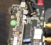
I did some probing around the Microprocessor board and those 2 conductive plastic caps appear to be in the 5V feed to the what I identified as a TPS7A4700 regulator (U6) which I believe is the pre-regulator before what I believe is the DC-DC converter (U3).
To get hot, either the voltage going into the stack is too high or it is drawing too much current. I'm assuming you have checked this, but if not, can you check the output voltage of the SMPS feeding the Microprocessor board? Easiest place to check is across the + & - terminals of the supercap on that board.
Also, can you measure the current draw of that 5V feed? @gtv4, looks like you did this already, was the voltage still at 5V?
Finally, can you check the temps on the 2 heat sinks, the one on U2 (microprocessor?) and U3 (DC-DC converter?)?
Thanks!
Greg in Mississippi
@marudo (and @gtv4),
I did some probing around the Microprocessor board and those 2 conductive plastic caps appear to be in the 5V feed to the what I identified as a TPS7A4700 regulator (U6) which I believe is the pre-regulator before what I believe is the DC-DC converter (U3).
To get hot, either the voltage going into the stack is too high or it is drawing too much current. I'm assuming you have checked this, but if not, can you check the output voltage of the SMPS feeding the Microprocessor board? Easiest place to check is across the + & - terminals of the supercap on that board.
Also, can you measure the current draw of that 5V feed? @gtv4, looks like you did this already, was the voltage still at 5V?
Finally, can you check the temps on the 2 heat sinks, the one on U2 (microprocessor?) and U3 (DC-DC converter?)?
Thanks!
Greg in Mississippi
- Home
- Vendor's Bazaar
- New FIFO buffer for RPI/SBCs