@Jonathan P, I forgot that also, a board revision would normally trigger a HW revision number change. ALL of your boards pictured are HW revision 1.2. Allo would absolutely have to change the board design (and would have changed that revision number) to have changed which pin on J31 takes the +5V input.
@marudo (and @gtv4),
I did some probing around the Microprocessor board and those 2 conductive plastic caps appear to be in the 5V feed to the what I identified as a TPS7A4700 regulator (U6) which I believe is the pre-regulator before what I believe is the DC-DC converter (U3).
To get hot, either the voltage going into the stack is too high or it is drawing too much current. I'm assuming you have checked this, but if not, can you check the output voltage of the SMPS feeding the Microprocessor board? Easiest place to check is across the + & - terminals of the supercap on that board.
Also, can you measure the current draw of that 5V feed? @gtv4, looks like you did this already, was the voltage still at 5V?
Finally, can you check the temps on the 2 heat sinks, the one on U2 (microprocessor?) and U3 (DC-DC converter?)?
Thanks!
Greg in Mississippi
In my case, thanks to Allo, the microprocessor board has been diagnosed & confirmed faulty (and will be replaced) - apart from everything else, it is NOT generating the +-15V feed. I was feeding the microprocessor from a 2.4A Apple charger outputting 5.08V and the microprocessor board on its own draws 1.81A.
My hope now is that the OpAmp & Isolator boards were no affected by all this happenings.
I must say that whilst I'm a bit disappointing at the problems, I also have to say that Allo's after sales service has been exemplary and their willingness/openness in acknowledging/ resolving issues will be a shock to retailers in my part of the world. To me, we're semi beta testing a cutting edge value for money (so i hope) product and I'm sort of OK with issues so long as the issues get resolved.
I couldnt agree more.. support is good from allo nowadays specially for an A1 streamer. I wont be investing on other streamers and transports.. Allo's SQ is addictive..In my case, thanks to Allo, the microprocessor board has been diagnosed & confirmed faulty (and will be replaced) - apart from everything else, it is NOT generating the +-15V feed. I was feeding the microprocessor from a 2.4A Apple charger outputting 5.08V and the microprocessor board on its own draws 1.81A.
My hope now is that the OpAmp & Isolator boards were no affected by all this happenings.
I must say that whilst I'm a bit disappointing at the problems, I also have to say that Allo's after sales service has been exemplary and their willingness/openness in acknowledging/ resolving issues will be a shock to retailers in my part of the world. To me, we're semi beta testing a cutting edge value for money (so i hope) product and I'm sort of OK with issues so long as the issues get resolved.
Jonathan are you in touch with support ?
Well I sent an email a few days ago to the same guys who sent me a replacement stack the first time but no answer yet. I guess they're still away for the holidays.
I was planning to ship the stack tomorrow to their canadian distributor like they asked me to do the first time.
@Jonathan P, I forgot that also, a board revision would normally trigger a HW revision number change. ALL of your boards pictured are HW revision 1.2. Allo would absolutely have to change the board design (and would have changed that revision number) to have changed which pin on J31 takes the +5V input.
@marudo (and @gtv4),
I did some probing around the Microprocessor board and those 2 conductive plastic caps appear to be in the 5V feed to the what I identified as a TPS7A4700 regulator (U6) which I believe is the pre-regulator before what I believe is the DC-DC converter (U3).
To get hot, either the voltage going into the stack is too high or it is drawing too much current. I'm assuming you have checked this, but if not, can you check the output voltage of the SMPS feeding the Microprocessor board? Easiest place to check is across the + & - terminals of the supercap on that board.
Also, can you measure the current draw of that 5V feed? @gtv4, looks like you did this already, was the voltage still at 5V?
Finally, can you check the temps on the 2 heat sinks, the one on U2 (microprocessor?) and U3 (DC-DC converter?)?
Thanks!
Greg in Mississippi
Hey Greg,
Just for clarity, in case it matters, on my Isolator board it shows HW revision 1.3.
For the photos of my setup, I posted a link to online album. Let me know it you can access it and if the photos are clear enough.
Dynamic Link Not Found
I'll try to do the continuity test and post the results but I don't have mu gear on hand.
I think it would be important to clarify John and cdsgames posts about inverted J31 / connector polarity because I don't want to fry it again! :|
Got the Katana today and using it with the isolator board. For now, using a LPS connected to the Micro Control board into the USB-C and the Allo SPMS PSU connected to the Isolator board at the USB-C. The player is connected to some power speakers so I can break it in. I use Moode Audio 4.4 yet I have issues. I can play internet radio stations without issue. I can NOT play individual tracks from the external HD yet I select a whole album, then I can play, WTF?
@gtv4 & @marudo, I'm glad Allo is taking care of you both. Let us know how you make out.
@Jonathan P, First, your link doesn't work. Send in a PM?
Unless your Katana DAC board has a HW Rev different than 1.2, I am absolutely certain that the positive connection is as I described. BUT it is always good to confirm that with a continuity check as I described... If you don't have a meter, I suggest getting an inexpensive one from someplace like Harbor Freight. Doing any sort of DIY work (and connecting wires like this is definitely DIY) you want a basic understanding of how to use a meter to measure continuity, resistance, and AC & DC voltages. You will save a lot of $$$ & frustration with these in your toolkit. Hooking up power to something you have a question about and haven't checked will eventually result in a 'destroy a board' failure.
Finally, the board revision does not correspond to the product number. See the Allo.com page for the Isolator 1.2, where the picture clearly shows the board rev as 1.3. A manufacturer may have many or no board revisions between different versions of a product... the original Katanas were released with rev 1.2 DAC boards and they were shown as such in the original manual, though they did not call it the Katana 1.2 at that time. The changes that led Allo to change the product name to the Katana 1.2 came after that version of the manual was written and released. Yet the Katana 1.2 still uses DAC board rev 1.2, which has the +5V connection as the one nearest the mounting hole and the last 'a' in Katana. That cannot be changed without creating a new version of the board.
BTW, who was your customer support contact at Allo before?
Greg in Mississippi
P.S. Why I'm certain of what I say about where the +5V pin is on the Katana rev 1.2 DAC board is that I have 4 of them here, 3 of which I've powered up and used. Some came with the brown lead (+5V) on the connector in the right place, some with it in the wrong place. I confirmed where it should go before connecting power on each. They all had the +5V pin where I described, even the ones with the power connector installed backward.
Last edited:
@LizardKing01, I suggest you direct that question to Tim Curtis of Moode directly in his Moode software thread here:
https://www.diyaudio.com/forums/pc-based/271811-moode-audio-player-raspberry-pi.html?highlight=moode
That is going to be controlled by the Moode software and has nothing to do with how the Katana works.
Sorry, I know nothing about Moode, so can't help you on this.
Just an FYI.
Greg in Mississippi
https://www.diyaudio.com/forums/pc-based/271811-moode-audio-player-raspberry-pi.html?highlight=moode
That is going to be controlled by the Moode software and has nothing to do with how the Katana works.
Sorry, I know nothing about Moode, so can't help you on this.
Just an FYI.
Greg in Mississippi
How can I update the firmware on the board. I have placed the two files on the SD card. The syntax I do not understand. I use putty as a SSH session.
@lizardking01,
Have I missed something? Did as Allo release a firmware update? I thought all Katanas were being shipped with the current firmware?
Greg in Mississippi
Have I missed something? Did as Allo release a firmware update? I thought all Katanas were being shipped with the current firmware?
Greg in Mississippi
BUT it is easy to check which way is correct with a quick continuity check. The positive side should have continuity to one of the pins on J30 AND to the 5V pins on the RPi GPIO header, 2 and 4. The ground side should have continuity to GPIO pin 6 (among others) AND to one side of almost ALL of the capacitors on the board (as most will have one side go to ground on this board... not so on the Opamp board). ALL of the Katana boards I have measure this way.
Greg in Mississippi
Hey Greg,
Do I have to detach Katana from the stack to perform your continuity test?
The results don’t seem to make sens so I assume I did not measure properly or maybe I got the wrong pins for GPIO2-4-6.
I added a photo to my album (Katana - Google Photos)
with wires in GPIO header for the pins I measured resistance between J31, J30 and caps.
Here’s a direct link to that photo:
Shared album - Jonathan Poitras - Google Photos
So here are some results:
Isolator J30 pin away from the mounting hole (towards the caps in the middle of the board)
J31 +: about 1.2 ohms
J31 -: about 60 ohms
GPIO2
J31 any of the 2 pins (+-): about 1600-1700 ohms
GPIO 4
J31 any of the 2 pins (+-): no continuity
GPIO6
J31 any of the 2 pins (+-): no continuity
2 big caps _- side) under Katana board (7N2222)
J31 +: about 50 ohms
J31 -: about 3 ohms
I did rest the micro controller boar, shut down the system. I can not play high rez files, only 16 bit CD's. Back to the Boss. Did i have a detective unit?
@Jonathan P
Some hints... First search online for Raspberry Pi GPIO Pinout to get a map of the pins on that connector so you are checking the right ones.
Second look for the pin numbers on the bottom of the Katana circuit board at the GPIO connector corners so you can match the map to the pins. Note that pin 1 is indicated by an arrowhead.
Third probe the fingers at the base of the GPIO connector. These are where each position of the GPIO connector are soldered to the board and easier to reach.
Fourth you are looking for zero or nearly zero ohms between the pin I indicated as the +5V one on J31 and one of the pins on J30 and pins 2 & 4 on the GPIO connector. Easiest to reach that J31 pin on the bottom of the Katana board.
Let us know how you make out.
Greg in Mississippi
I did rest the micro controller boar, shut down the system. I can not play high rez files, only 16 bit CD's. Back to the Boss. Did i have a detective unit?
@LizardKing01
It is very likely that the issue(s) stems from the Moode OS i.e. the way it has been configured. In order to eliminate other possible causes:
- make sure that your Katana kit is set-up in the simplest configuration (no Isolator board and minimal number of PSUs)
- a re-stacking of the boards could help with possible contact problems
- re-flash the Moode OS (if possible on a new uSD card)
- configure Moode OS as per the set-up instructions on the GitHub (ReadMe.md -> Setup Guide) and hold on to setting up a music source
- after testing the audio with the internal test try several Radio stations
- if positive, load several albums of different bit rates and mixture of format (mp3, flac, etc) on a freshly formatted USB memory stick and test the stick on a different computer
- test the RPI/Katana combo with the USB stick
- if the problem persists try build a Volumio image on a uSD card and re-run the test
- if the new test is positive seek help on the Moode forum
- if the new test is negative I'm lost for words and ideas but let's be positive and try to be as accurate as possible in your testing... do not make more than one modification at a time before rebooting Moode and testing again.
Let us know one way or another...
-
@LizardKing01, I suggest you direct that question to Tim Curtis of Moode directly in his Moode software thread here:
Moode now has its own Forum, so it's best to ask there: Moode Forum
@Greg Stewart,
I sent you the link in PM and I'll give it another try here:
Katana - Google Photos
My customer support contact people were:
Can’t agree more. I’ill work on it!
I think I have a decent multimeter but one of the probes is broken so it’s hard to get reliable readings.
I still get some K/Mohms readings where I shouldn't but I suspect it’s due to my broken meter probe and my fingers touching the probe points.
So using a 200 ohms range threshold to identify open/close circuits, here’s what I read:
Note: positive side = the side shown in my photos that you identified as the side closer to the mounting hole close to the last “a” in “Katana” printing.
If I understood correctly, that would mean that the culprit is not this J31 connector/cable.
Who could the culprit be then?
@Jonathan P, First, your link doesn't work. Send in a PM?
I sent you the link in PM and I'll give it another try here:
Katana - Google Photos
BTW, who was your customer support contact at Allo before?
My customer support contact people were:
- ruby@allo.com
- ravips@cem-solutions.net
...BUT it is always good to confirm that with a continuity check as I described... If you don't have a meter, I suggest getting an inexpensive one from someplace like Harbor Freight. Doing any sort of DIY work (and connecting wires like this is definitely DIY) you want a basic understanding of how to use a meter to measure continuity, resistance, and AC & DC voltages. You will save a lot of $$$ & frustration with these in your toolkit. Hooking up power to something you have a question about and haven't checked will eventually result in a 'destroy a board' failure.
Can’t agree more. I’ill work on it!
I think I have a decent multimeter but one of the probes is broken so it’s hard to get reliable readings.
BUT it is easy to check which way is correct with a quick continuity check. The positive side should have continuity to one of the pins on J30 AND to the 5V pins on the RPi GPIO header, 2 and 4. The ground side should have continuity to GPIO pin 6 (among others) AND to one side of almost ALL of the capacitors on the board (as most will have one side go to ground on this board... not so on the Opamp board). ALL of the Katana boards I have measure this way.
I still get some K/Mohms readings where I shouldn't but I suspect it’s due to my broken meter probe and my fingers touching the probe points.
So using a 200 ohms range threshold to identify open/close circuits, here’s what I read:
- positive side => J30 => GPIO 2/4: continuity
- ground side => GPIO 6 / CAPS: continuity
Note: positive side = the side shown in my photos that you identified as the side closer to the mounting hole close to the last “a” in “Katana” printing.
If I understood correctly, that would mean that the culprit is not this J31 connector/cable.
Who could the culprit be then?
- My other Katana J31 connector/cable with reversed polarity? And I got lucky in my first test but not in my second?
- Loose Katana J30 jumper
- Wrong MC J27 settings? All open, according to the manual
- iPower know to fry connected gear?
I hooked up my Allo Bos dac 1.2 and that works fine! Both are using Moode 4.4
@LizardKing01
It is very likely that the issue(s) stems from the Moode OS i.e. the way it has been configured. In order to eliminate other possible causes:
- make sure that your Katana kit is set-up in the simplest configuration (no Isolator board and minimal number of PSUs)
- a re-stacking of the boards could help with possible contact problems
- re-flash the Moode OS (if possible on a new uSD card)
- configure Moode OS as per the set-up instructions on the GitHub (ReadMe.md -> Setup Guide) and hold on to setting up a music source
- after testing the audio with the internal test try several Radio stations
- if positive, load several albums of different bit rates and mixture of format (mp3, flac, etc) on a freshly formatted USB memory stick and test the stick on a different computer
- test the RPI/Katana combo with the USB stick
- if the problem persists try build a Volumio image on a uSD card and re-run the test
- if the new test is positive seek help on the Moode forum
- if the new test is negative I'm lost for words and ideas but let's be positive and try to be as accurate as possible in your testing... do not make more than one modification at a time before rebooting Moode and testing again.
Let us know one way or another...
-
Katana is working fine!!!!!!! I had to disassemble all of the 5 boards them reconnect them minus any standoffs or screws. As a test and also for break in, I have them going to some powered speakers that I use with my HDTV. No software Changes at all. Using a 4.0 tb hard drive and music is flowing.
@LizardKing01
It is very likely that the issue(s) stems from the Moode OS i.e. the way it has been configured. In order to eliminate other possible causes:
- make sure that your Katana kit is set-up in the simplest configuration (no Isolator board and minimal number of PSUs)
- a re-stacking of the boards could help with possible contact problems
- re-flash the Moode OS (if possible on a new uSD card)
- configure Moode OS as per the set-up instructions on the GitHub (ReadMe.md -> Setup Guide) and hold on to setting up a music source
- after testing the audio with the internal test try several Radio stations
- if positive, load several albums of different bit rates and mixture of format (mp3, flac, etc) on a freshly formatted USB memory stick and test the stick on a different computer
- test the RPI/Katana combo with the USB stick
- if the problem persists try build a Volumio image on a uSD card and re-run the test
- if the new test is positive seek help on the Moode forum
- if the new test is negative I'm lost for words and ideas but let's be positive and try to be as accurate as possible in your testing... do not make more than one modification at a time before rebooting Moode and testing again.
Let us know one way or another...
-
Katana is working fine!!!!!!! I had to disassemble all of the 5 boards them reconnect them minus any standoffs or screws..............
 🙂
🙂@LizardKing01... Congratulations. Glad to hear you got it to work ok.
@Jonathan P... I’m glad you got some readings that let you confirm for yourself what I said about which pin on the J31 connector on the Katana DAC board is the positive one. Learning how to do that type of measurement (and what points to measure between) will go a long way towards successful DIY’s).
A couple of observations… for checking continuity, you want to use the lowest ohm range on your meter. IF you are reading K-ohms or M-ohms, you are in a range that can give you not very useful readings. Again, for continuity you are looking for a 0R or near 0R reading. Second, replace that set of leads with the broken probe ASAP! That your fingers got involved in the measurement of course gave you some not-very-useful readings… AND in some situations, could be dangerous to you or the gear you are measuring. While you don’t have to have the best and most expensive test gear for basic DIY purposes (here in the US, a meter from the low-cost tool retailer Harbor Freight that sells for <$10USD is sufficient for many DIY purposes), you MUST have properly functioning gear AND gear that does not expose you to the voltages being measured.
As for your question on the culprit for your Katana failures, you’ve have not provided sufficient information for me to make any determination of what caused them. Based on your Google Drive pictures, I know that the cable on the Katana shown in the pictures on your Google Drive (where you can see both the J31 plug and the power plug you installed on the wires) is installed in the right polarity… the brown wire goes to the side of the J31 closest to the mounting hole and the last ‘a’ in Katana AND to the positive side of the power connector you wired in. BUT some Katanas have the socket on the J31 turned 180 degrees when they were installed. You show 2 different plugs on the J31 power cable in your Google drive pictures… 1 looks like it is setup to work on the Katana DAC board that you showed while the other is backwards for that DAC board’s plug. BUT it would work ok on the DAC boards with the J31 socket turned the other way. From your descriptions of your trials, I don’t know which way the plugs were oriented on the Katana DAC boards in each trial and if a J31 cable was used that fed the power in the correct polarity for that Katana DAC board. Going forward, hopefully, using your meter, you can now confirm:
- Which side of the Katana J31 socket is the positive side.
- That you wired your power connector on the end of the J31 power cable in the right polarity.
- That the power supplies you used have their output connectors wired in the right polarity for that setup.
Those basic checks can and should be used with any setup where you are wiring power yourself instead of using a power supply and powered unit that were provided by the manufacturer ready to use. AND it isn’t a bad idea to use them even when you receive a pre-wired setup… they aren’t always right!
I hope this all helps!
Greg in Mississippi
Last edited:
As for your question on the culprit for your Katana failures, you’ve have not provided sufficient information for me to make any determination of what caused them. Based on your Google Drive pictures, I know that the cable on the Katana shown in the pictures on your Google Drive (where you can see both the J31 plug and the power plug you installed on the wires) is installed in the right polarity… the brown wire goes to the side of the J31 closest to the mounting hole and the last ‘a’ in Katana AND to the positive side of the power connector you wired in. BUT some Katanas have the socket on the J31 turned 180 degrees when they were installed. You show 2 different plugs on the J31 power cable in your Google drive pictures… 1 looks like it is setup to work on the Katana DAC board that you showed while the other is backwards for that DAC board’s plug. BUT it would work ok on the DAC boards with the J31 socket turned the other way. From your descriptions of your trials, I don’t know which way the plugs were oriented on the Katana DAC boards in each trial and if a J31 cable was used that fed the power in the correct polarity for that Katana DAC board. Going forward, hopefully, using your meter, you can now confirm:
- Which side of the Katana J31 socket is the positive side.
- That you wired your power connector on the end of the J31 power cable in the right polarity.
- That the power supplies you used have their output connectors wired in the right polarity for that setup.
Hi Greg,
Thanks for you answers.
All photos in my google album show the setup for the last Test I performed, with the cable on the right in the image with the 2 J31 cables/connectors you mentioned.
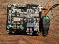
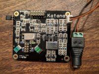
For clarity, here are photos of the 2 cables connected to Katana:
- cable1 photo (RED wire on top close to mounting hole)
- cable2 photo (BLK wire on top close to mounting hole)
- All setup photos
Just before this last test, I also did the exact same test with the same boards, supplies and jumper settings. The only difference was to use cable2 instead of cable1. Not so smart, agreed! The connectors on cable2 were super loose so I thought it could be defective and switched cable2 with cable1, obviously without noticing they had opposite polarity. Didn't notice either the + sign on the board hidden under J31 connector :|
Note: I read 5V at the end of both cable1 and cable2 between brown and black wires so I assume the PSU polarity and provided black/green barrel connectors I attached to cable1 and cable2 are connected properly.
Logically, if my readings are valid, it should mean that it's this previous test with cable2, that is more likely to be the culprit, or J37 on MC or something else, right?
How to tell if this is the case? Are my photos and continuity checks sufficient to confirm it’s ok in my case?BUT some Katanas have the socket on the J31 turned 180 degrees when they were installed
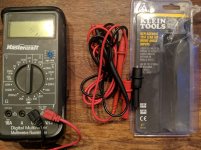
FYI, I followed your advice and got a new set of top notch (I believe) Klein Tools leads with removable clip extensions for my multimeter 🙂
Attachments
- Home
- Vendor's Bazaar
- New FIFO buffer for RPI/SBCs