Have just checked the resistance to 0v from pin 5 of the suspect regulator and found it to be high. Applied 4.7 volts to its output and circa 130mA flowed into the DAC and the power LED lit.
I still can't explain why pins 2 and 4 of the GPIO from the Rpi +5v rail are permanently connected to the power input pin of J31. Looks like an inherent fault with the board. when I first connected recommended dual power arrangement to the Katana stack and fed the +/-15 volts to the opamp board the combined Microcontroller board and Katana boards only drew 52 mA. Where was the remainder of the 130mA or more required by the Katana DAC actually coming from in dual power mode? It could have only have been sourced from the RPi GPIO pins no 2 and 4 which are coincidently both connected to the Katanas 5v power rail on my boards regardless of whether J30 is fitted or OC.
If the isolator is fitted then I think pins 2 and 4 of the GPIO should not be fed by the isolator and that side of the isolator gets clean power from the Katana, which is probably why Greg and anyone else using the isolator has not experienced this failure.
Tomorrow I'll see if I can bypass the faulty regulator and disconnect pins 2 and 4 of the GPIO. If no other damage has been done then the Katana DAC should work again and a design/application fault will have been revealed.
Ho hum...
Last edited:
which is probably why Greg and anyone else using the isolator has not experienced this failure.
Don't know about that. I had Katana 1.0 and 1.1 here for review and had it hooked up to various combinations of power supplies, including bringing in 5v on the red/black wires to the connector on the Katana board. It always worked okay for me but I didn't use an LDO, only a 7805 linear supply for the Katana board.
Don't know about that. I had Katana 1.0 and 1.1 here for review and had it hooked up to various combinations of power supplies, including bringing in 5v on the red/black wires to the connector on the Katana board. It always worked okay for me but I didn't use an LDO, only a 7805 linear supply for the Katana board.
Maybe that was a bit hasty of me. Should wait until I see a schematic. I didn't expect to see pins 2 and 4 of the GPIO connector from the Rpi connected to the Katana when no jumper J30 is fitted. I guess there could be some sort of switched interlock working through the Micro Controller board.
Sorry to ask but do you recall if you were using the isolator when you powered the Katana through the J31 connector with 5v? If you or anyone else did without a failure then I must be wrong. I really do need to know what causes this failure, especially as it happened twice.
BTW have just confirmed the same LDO failure on the first Katana board and circa 100mA and a lit power LED when 4.7 volts is applied directly to said LDO's output pin.
How are the Xmas decs looking

John
There were no isolators for Katana back then that I know of. If there were, I didn't have one in any case. Katana was sent to me for review, and it was just the three Katana boards that came in the shipping package.
Hi Mark,
Do you use ak4137 and upsample to dsd256 with the katana?
@John Luckins / @Markw4,
First, I didn't get an isolator until late August, as I remember. I don't believe they were available before then, remember Allo had to change the design to enable 2-way communications on some of the lines... I2C maybe?
Second, I just checked the original Katana DAC board I have here still (like Markw4) and I do not have any connection to GPIO pins 2 & 4 from the J31 5V input connection if the J30 jumper is not on.
AND I don't see a way even a fault could bridge them, I probed all of the LDO's and found nothing connected to those GPIO pins. The only permanently connected components are the 3 larger and 1 smaller local reservoir caps on the bottom of the board. BUT bridge it did, somehow and someway. The mystery persists.
Greg in Mississippi
Last edited:
Hi Mark,
Do you use ak4137 and upsample to dsd256 with the katana?
No. There are various reasons why not. Mostly, Katana is not designed to be used that way. I upsample with modded dacs in the other thread only.
Regarding the power jumper on the first, old Katana board here, the red external power wire and the pins connected to it that go up to the MCU board on the board edge pin header, they both connect to one of the pins on the power jumper, the one more towards the middle of the Katana board. The other pin on the power jumper goes somewhere unknown at the moment. I didn't try to trace it.
However, I wonder if the jumper might bypass the regulator that failed? If getting power from the MCU board, then Katana might not need another series regulator, maybe that function is or would be done on the MCU board instead? Just wondering what someone might have been thinking.
Haven't tried looking at it on the new Katana board that just arrived two days ago.
Last edited:
@Markw4, your mystery jumper pin is the one that connects to the GPIO pins 2 & 4 & the caps on the bottom of the board.
The other pin you mention does connect to John's failed mystery regulator expected input and enable pins. AND as far as I can find, all of the other regulators are either fed from the mystery regulator OR cascaded from one of the other downstream regulators. SO John's mystery regulator is the series and likely single point of failure for John's board. Curious what chip it is? I too looked and couldn't find a reference to the markings.
Also, AFAIK, there is only 1 manufactured run of boards out there. The Katana 1.2 boards have been modified to encorporate the various upgrades, but I believe they are still the same basic board design and likely even the same board run.
AND AFAIK, there were no modifications to the DAC board for 1.2, which to me is a tribute to how well Allo did on the design and layout on the part that was most like their previous designs. It was only in the output stage (and a complex discrete one at that!) and the power filtering around the microprocessor and DC-DC converters that they ended up making further improvements.
Greg in Mississippi
P.S. AND before anyone asks, I DO NOT have the schematics to the Katana!
Last edited:
No. There are various reasons why not. Mostly, Katana is not designed to be used that way. I upsample with modded dacs in the other thread only.
Thank you for your answer.
Is it because Katana runs in master mode or is it for another reason?
A small but perhaps important correction to what I reported earlier. I did not find continuity between the red (+ve) power input on the Katana board and pins 2 and 4 on the GPIO to the RPi. What I detected was the same voltage on pins 2 and 4 of the GPIO as was being fed to the red input power lead (the one connected nearest to the GPIO header). I think the difference might be very significant and I'm sorry to have reported it incorrectly as continuity. It was late here and I should have checked directly for continuity as well.
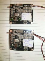
To spice things up further though I have just noticed this...
https://www.diyaudio.com/forums/attachment.php?attachmentid=717935&stc=1&d=1543167376
Apart from the labels can you spot the difference. Note that both connector males are properly orientated in their sockets and both of the flying leads are as supplied by Allo. Ooops!
The upper lead was supplied most recently. The lower lead came with my original Katana. I'm upset again.
John
Attachments
Last edited:
Thank you for your answer.
Is it because Katana runs in master mode or is it for another reason?
When we use AK4137, the output is in I2S format, but Katana gets I2S inputs come from RPi. RPi has to tell Katana MCU what sample rate the file is, then Katana configures the clocking for that sample rate. Then Katana generates clock signals that RPi uses to send the audio I2S data bits.
To connect up AK4137, we would have to intercept I2S between RPi and Katana and intercept their communications. Katana would need to know to expect DSD for all files and generate clocks for that. AK4137 would have to be modified to accept clocking from Katana. We would have to generate our own clocks for RPi at the correct sample rate for the file in order to make RPi send the I2S data to AK4137.
If you think modifying one of the cheap Chinese dacs is complicated and time consuming, trying to use AK4137 with Katana would probably be worse.
John,
I understand your upset and frustration. I have seen this too... 2 of the 4 Katana I have here now had the plug oriented one way, the other 2 the other way. I immediately reported such to Allo. I don't remember that any had the wires oriented that that black would be into the positive side, but I could have just swapped it on the plug and moved on. Those experiences were why I asked about the power feed into the DAC board in my PM to you.
My personal practice on things such as this is to report it to the vendor and leave them to improve their QC AND deal with it in the field where needed. That's why I didn't report it here. A very good thing is that Allo has been very responsive and generous in updating their DAC to bring it up to expected performance, providing replacement units plus goodies after the updates, and providing replacements where their quality control has been insufficient, whether they caused an issue (such as you experienced) or not. If they had not been such, I'd be one of the first to raise an alarm.
John, I fully expect Allo will respond postively to what you've found and experienced. I just hope they can do more to improve their QC such that these issues don't occur OR are caught before the units 'escape' to us customers. Being in the aviation and aerospace manufacturing sector, I know this is one of the constant struggles manufacturers deal with. THE most dreaded failures are ones that occur in the QC area where they don't catch serious issues before release to the customer (escapes). Of course, Allo's QC issues don't result in aircraft / helicopters / satellites falling out of the sky... at least so far!
THAT, BTW, is what keeps ME up at night!
Greg in Mississippi
If you think modifying one of the cheap Chinese dacs is complicated and time consuming, trying to use AK4137 with Katana would probably be worse.
Hahaha! I think that you are right
")
Thank you the the very clear explanation.
Better pictures of problematic Katana:
https://www.diyaudio.com/forums/att...1543090516-fifo-buffer-rpi-sbcs-sany0665a-jpg
https://www.diyaudio.com/forums/att...1543090519-fifo-buffer-rpi-sbcs-sany0669a-jpg
https://www.diyaudio.com/forums/att...1543090519-fifo-buffer-rpi-sbcs-sany0674a-jpg
https://www.diyaudio.com/forums/att...1543090519-fifo-buffer-rpi-sbcs-sany0675a-jpg
https://www.diyaudio.com/forums/att...1543090519-fifo-buffer-rpi-sbcs-sany0676a-jpg
https://www.diyaudio.com/forums/att...1543090519-fifo-buffer-rpi-sbcs-sany0677a-jpg
Thanks for looking...
John
Hi John
.... in your pic the cable has 2 polarities inverted. We are checking our stock , here in EU we have no such cable , but in India they already found a few. Seems that our chinese manufacturer , inverted wires on some unit.
Please send me the order number and I will courier it today.
Hi Cdsgames,
I just received my Katana 1.2 from euro stock.
Very fast shipping but I have a problem.
I received only one of the two output stages that I ordered.
I will contact allo support this afternoon about this issue.
Is there a way to know which output stage I received?
what are visual differences between pure thd and sound quality?
thank you for your help
- Home
- Vendor's Bazaar
- New FIFO buffer for RPI/SBCs