Using Triple power sources damages Katana - twice
Using Triple power sources damages Katana - twice.
I wonder if anyone can help explain something that has now happened to me twice, first on the initial version of Katana, and now on its new version replacement...on the first occasion I send a PM to cdsgames but got no response. I guess he was very busy at the time🙂
As per the manual I opened jumper J3 on the Katana board, removed the jumper J26 on the Micro Controller board and then followed the power up sequence of Katana first, then MC and then RPI. Each supply was a well tested LT3042 supply with pnp pass transistor. Each had been used on earlier Allo DACs successfully and was checked to be good for the expected load current. The result of doing this was a flashing status light on the Microcontroller board and an unlit power LED on the Katana board.
Reverting to the dual supply setup used successfully before yields the same result now indicating damage has been done by following the manual to the letter for the triple power feed. The Katana board is now no longer being powered up and the RPi doesn't recognise the Katana DAC at all as a result (squeezelight fails to load in PiCorePlayer). Perhaps this is the reason why the triple power option is "not recommended ?? I don't know.
Obviously I am upset to put it mildly, but the sound I was previously getting from the two supply option was excellent and obviously better than any previous Allo DAC (I own and use Boss, miniBoss and 2 X Piano DACs), so there is still hope and optimism for Katana here. I had planned to feed the triple power option with multiple Super-regs which had been very good when feeding a my previous best DAC, the Dial DAC and each of the other Allo DACs. If this can't be done then I would feel the Katana to be somewhat hobbled.
I wonder if Allo could please investigate/test the triple power option and confirm that the settings stated in the manual do indeed work reliably, whether there are any pitfalls and perhaps suggest what I and perhaps others in the future might be doing wrong. I rather think I am due a replacement Katana as lightning has struck twice here but I am nervous about its ability to cope with the triple supply option which should yield the best sound quality.
Has anyone else here had success with the triple power option - I wonder??
John
@John Luckins
How are you powering the op amp boards for your configuration? Was the +/- 15V supplied externally or from the micro controller?
BTW you did mean J30 and not J3 on the Katana board?
Regards
How are you powering the op amp boards for your configuration? Was the +/- 15V supplied externally or from the micro controller?
BTW you did mean J30 and not J3 on the Katana board?
Regards
@John Luckins,
It's not clear if you were using the Isolator or not? Can you confirm and if so, confirm your jumper settings on it?
Also can you send pix of your power feeds into the Katana, especially into the DAC board?
To answer your question, yes I have run them here with 3 supplies a number of times. My settings when I'm doing this:
On the Microprocessor board:
- Sw3 on
- jumpers on J28 & J29 pins 2&3
- no jumpers on J31 & J26 (J31 shouldn't matter, but J26 does)
- 5V into the USB-C connector
On the DAC board:
- jumper on J30 (To power the Isolator secondary or output side)
- Power into J31 (mind the polarity!)
On the Isolator board:
- NO jumper on J26 (RPi feeds power to the primary or input side of the Isolator)
Another thing to note… with the Supercaps on the DAC and Microprocessor boards, circuits can stay powered for several minutes AFTER you disconnect the power from the boards. When I switch over between 3-supply and 4-supply modes very quickly, when I first power up the stack the status LED will flash on the Microprocessor board. I have to un-power the entire stack and let it sit for 5-7 minutes before I can successfully power it up again.
Looking forward to seeing some pix of your setup!
Greg in Mississippi
Using Triple power sources damages Katana - twice.
I wonder if anyone can help explain something that has now happened to me twice, first on the initial version of Katana, and now on its new version replacement...on the first occasion I send a PM to cdsgames but got no response. I guess he was very busy at the time🙂
As per the manual I opened jumper J3 on the Katana board, removed the jumper J26 on the Micro Controller board and then followed the power up sequence of Katana first, then MC and then RPI. Each supply was a well tested LT3042 supply with pnp pass transistor. Each had been used on earlier Allo DACs successfully and was checked to be good for the expected load current. The result of doing this was a flashing status light on the Microcontroller board and an unlit power LED on the Katana board.
Reverting to the dual supply setup used successfully before yields the same result now indicating damage has been done by following the manual to the letter for the triple power feed. The Katana board is now no longer being powered up and the RPi doesn't recognise the Katana DAC at all as a result (squeezelight fails to load in PiCorePlayer). Perhaps this is the reason why the triple power option is "not recommended ?? I don't know.
Obviously I am upset to put it mildly, but the sound I was previously getting from the two supply option was excellent and obviously better than any previous Allo DAC (I own and use Boss, miniBoss and 2 X Piano DACs), so there is still hope and optimism for Katana here. I had planned to feed the triple power option with multiple Super-regs which had been very good when feeding a my previous best DAC, the Dial DAC and each of the other Allo DACs. If this can't be done then I would feel the Katana to be somewhat hobbled.
I wonder if Allo could please investigate/test the triple power option and confirm that the settings stated in the manual do indeed work reliably, whether there are any pitfalls and perhaps suggest what I and perhaps others in the future might be doing wrong. I rather think I am due a replacement Katana as lightning has struck twice here but I am nervous about its ability to cope with the triple supply option which should yield the best sound quality.
Has anyone else here had success with the triple power option - I wonder??
John
Hi
did you use 5V on all 3 ?
Thanks for the quick response to my post guys.
To answer the questions raised in order:
ktham - The first Katana that failed was using the MC's internal +/- 15 volt supply, the second had a separate LM317/337 Twisted pair dual supply feeding it as had been the case when it was when it had just two 5v supplies. You are right, I did mean J30 (typo).
Greg - I wasn't using the isolator on the second occasion of failure. I didn't want to risk it. I'll send pics of the power feeds shortly though I have disconnected them now. To keep things simple I'll just relate the settings for the second failure (yesterday).
On the MC board:
SW3 was off as I was using the previously tested +/-15v supply.
J28 and J29 jumpers were shorting pins 1 and 2 for the external supply.
J26 had been removed.
J31 was closed.
DAC
J30 jumper was off as no isolator or Rpi power to be supplied
J31 was orientated as per the connector cut out and the pictures in the manual. The polarity had been double checked and 5.0 volts was supplied.
Isolator
There was none.
From my experience of powering DACs from LT3042 and Super-reg supplies I have been concerned about our lack of knowledge about the loads presented to these multiple supplies. Feedback regulators in particular only function correctly into a narrow range of loads. The load capacitance/ESR and the current draw range are almost complete unknowns with the Katana.
When the second stack failed in triple (5v)power mode I removed all supplies and took time to revert to the previous working dual supply config. That should have been long enough for the caps to drain. I did notice how long the MC's LED's stay lit for after removing power. If this has somehow been a cause of my failures it is a shame there has been no mention of it in the manual so far.
Pics to follow and perhaps a drawing of the setup at failure as well.
Thanks to you all
John
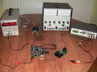
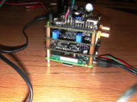
OK here's some pictures of the setup as it was when the Katana failed:

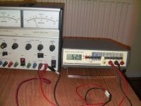
From left to right, 5.05 volts feeding 55mA to the Microcontroller then a TP split rail +/- 15volt supply feeding 73mA per rail to the J27 feed to the Opamp board. The big Farnell PSU is supplying 8 volts at 59mA to a LT3042 regulator board with a 3 Amp capable pass transistor. This is fed to the two pin connector J31 on the Katan board.
The power LED is lit on the MC board but the status LED is blinking at speed. The power LED on the Katana never lights at any stage in spite of its board drawing 52.9mA.
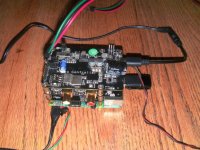
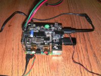
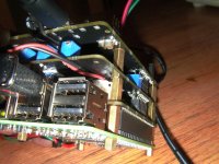
Here's a picture to show the jumpers on the MC.
J30 is open and the polarity of the feed to the Katana board has been double checked.
I now have two useless Katana stacks for repair and no understanding of how this can be done or how to prevent it from happening a third time.
I wonder what Allo Technical Support make of this?
From left to right, 5.05 volts feeding 55mA to the Microcontroller then a TP split rail +/- 15volt supply feeding 73mA per rail to the J27 feed to the Opamp board. The big Farnell PSU is supplying 8 volts at 59mA to a LT3042 regulator board with a 3 Amp capable pass transistor. This is fed to the two pin connector J31 on the Katan board.
The power LED is lit on the MC board but the status LED is blinking at speed. The power LED on the Katana never lights at any stage in spite of its board drawing 52.9mA.
An externally hosted image should be here but it was not working when we last tested it.
Here's a picture to show the jumpers on the MC.
An externally hosted image should be here but it was not working when we last tested it.
J30 is open and the polarity of the feed to the Katana board has been double checked.
I now have two useless Katana stacks for repair and no understanding of how this can be done or how to prevent it from happening a third time.
I wonder what Allo Technical Support make of this?
Last edited:
Posted once more with correctly added photos (and added feeling!):
OK here's some pictures of the setup as it was when the Katana failed:
https://www.diyaudio.com/forums/attachment.php?attachmentid=717674&stc=1&d=1543081070
From left to right, 5.05 volts feeding 55mA to the Microcontroller then a TP split rail +/- 15volt supply feeding 73mA per rail to the J27 feed to the Opamp board. The big Farnell PSU is supplying 8 volts at 59mA to a LT3042 regulator board with a 3 Amp capable pass transistor. This is fed to the two pin connector J31 on the Katan board.
The power LED is lit on the MC board but the status LED is blinking at speed. The power LED on the Katana never lights at any stage in spite of its board drawing 52.9mA.
https://www.diyaudio.com/forums/attachment.php?attachmentid=717675&stc=1&d=1543081070
Here's a picture to show the jumpers on the MC.
https://www.diyaudio.com/forums/attachment.php?attachmentid=717676&stc=1&d=1543081070
J30 is open and the polarity of the feed to the Katana board has been double checked.
I now have two useless Katana stacks for repair and no understanding of how this can be done or how to prevent it from happening a third time.
I wonder what Allo Technical Support make of this?[/QUOTE]
Please let me know if higher res piccies would help.
John
Attachments
Last edited:
I will check on Monday.
No problems and thanks for being around on a weekend.
John
@John Luckins
Clarification requested on J27 wiring on micro controller board for +/-15 V external op amp supply.
My actual measurements show a startup peak of about 98ma and then settling to 89ma on the 15V rail for an external supply.
For J27 Pins 1, 2 and 3 how is the external +/-15V sequence connected/soldered to these pins. Did you follow the board designations or the Katana manual?
I tried sorting this out by looking at the pictures but the required details/angles were unavailable. Thanks
Thanks for asking ktham.
J27 is direct soldered positive 15v to pin 1 and negative 15v to pin 3 common 0v is to the centre pin no2 . The external supply has the centre tap shorted between the two feeds on the underside of the regulator board. This board was previously used in supplying a constant 133mA to a class A headphone amp. It is fed by bridge rectified 24-0-24v DC and has a simple 2.2ohm 1000uF rc filter before each standard LM317 regulator. As a precaution I have checked the voltage is consistent on start-up and it is. I'll take a few more higher res photos and post shortly. It might be worth bearing in mind that on the first Katana failure of this type the Micro-controller board was supplying the +/-15 volt supply.
How much was/is your steady state current consumption from your external opamp supply. Was it approx. 73mA perchance?
Grateful
John
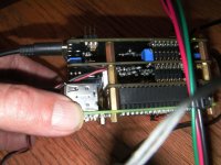
Better pictures of problematic Katana:
https://www.diyaudio.com/forums/attachment.php?attachmentid=717699&stc=1&d=1543090516
https://www.diyaudio.com/forums/attachment.php?attachmentid=717700&stc=1&d=1543090519
https://www.diyaudio.com/forums/attachment.php?attachmentid=717701&stc=1&d=1543090519
https://www.diyaudio.com/forums/attachment.php?attachmentid=717702&stc=1&d=1543090519
https://www.diyaudio.com/forums/attachment.php?attachmentid=717703&stc=1&d=1543090519
https://www.diyaudio.com/forums/attachment.php?attachmentid=717704&stc=1&d=1543090519
Thanks for looking...
John
Attachments


Better pictures of problematic Katana:
/QUOTE]
Thank you. Center conductor on barrel to USB-C adapter was rung out to verify + ?
Reddish/Brown wire to connector on Katana board is + ?
Just checking 🙂
Do you have a scope?
Last edited:
Yes and Yes Mark. USB-C was unchanged from previous working config. After the first failure I triple checked the Katana feed polarity.
I have a picoscope and connected laptop ready to roll and have finally mastered photo posting! spectrum analysis possible as well. With no circuit diagram what to probe??
Thanks
John
I have a picoscope and connected laptop ready to roll and have finally mastered photo posting! spectrum analysis possible as well. With no circuit diagram what to probe??
Thanks
John
Do you have any idea what board or boards may be damaged? If you think you have a dead katana board, we could start with it. It can be detached from the other boards, and 5v applied to the power connector. Judging by the case marking, some of the ICs on the board may be these voltage regulators: https://www.torexsemi.com/file/en/technical-support/discontinued/-2016/52-XC6219_11.pdf If so, you could measure the input/output/enable pins on them to see if any that should be working are working. There are a couple over by the dac chip where the film caps and super caps are connected to the AVCC pins. AVCC is fed up through the pin header there along with the dac chip analog outputs. The dac chip itself will need power to its for DVCC and VCCA too. One of the clocks and the clock distribution drivers next the the clock shield can will need to be powered up and enabled for the dac to be clocked. The enables for the clocks probably come down through the bigger pin header along one side of the board. You might be able to ring out those signals. Clock buffers are probably these: https://www.onsemi.com/pub/Collateral/NB3L553-D.PDF
Last edited:
@John Luckins
Thank you for the clearer pics.
I am assuming that the pics represent the configuration at time of "failure".
The Twisted Pear LCBPS in the pic shows a 4 terminal strip with the following being used. Blk wire to neg GND, Grn wire to '-' ve and red wire to '+'ve. GND on the '+' ve terminal is spare.
On the micro controller J27 you show Red wire on Pin 1 which is +15V in. Grn wire goes to 0V which is Pin 2, Blk wire to Pin3 which is -15V.
Looks like the Grn and Blk wires on the LCBS are reversed. Have a look at the LCBS documentation for the layout as the current Twisted Pear documents do not show the version of board you have.
On another point of interest for the RPI and peripherals, I use 5.2VDC as a standard supply.
This is more fun than hanging Xmas lights. Wifey thinks otherwise.
Regards
Hi ktham
All helpful questions to at least ensure that I'm not going potty here.
Yes that was the config at the time of the failure of the second unit.
The LCBPS is a dual LM317 regulator. From left to right its outputs are GND, +. GND, +. By connecting the two centre output terminals together and feeding it from two independent secondaries it then becomes a floating 15-0-15 volt supply. Not clear even from the better photos. The black wire is connected to the most negative rail of the left hand regulator, 15 volts below the centre green wire. Red cable is connected to the most positive rail of the device, +15volt. I have verified this is so when connected to the Katana and monitored its voltages at start up. The =/- 15 volts is maintained. The unit is unchanged from when it supplied +/-15 volts to a split rail headphone amp which drew a steady 130mA.
Good point about a raised supply voltage for the 5v rails perhaps 4.97v is a bit low for the Katana feed. 5.1 is probably OK for the Micro controller and worked well in the earlier and recommended dual supply setup.
Following Marks suggestion above I'm now feeding the standalone Katana board which had an unlit power LED and drew little current. I'm measuring each of the onboard LDO's for input and output voltage. The incoming 4.97 volts is not even reaching the their input terminals. I'll post a spreadsheet of the results as there are quite a few of them.
I only get away with this as wifey is addicted to strictly. Sadder still eh.
Cheers for your help.
John
Some progress on the bare Katana DAC testing.
Feeding the DAC with 4.97 volts, all nine LDO's have an input voltage of 0.76 volts or less. their outputs vary between 0.83 and 0.02 volts. With or without the jumper J30 fitted pins 2 and 4 of the GPIO connector to the Rpi are at 4.97 volts. Not good.
Adjacent to J30 is what appears to be a further SOT-25 regulator with the markings 58A 561. Its pins are at the following voltages:
1 4.97v
2 0v
3 1.51v
4 4.97v
5 0.773
I suspect this is a regulator to output the feed to J30 from its pin 4, and perhaps 3.3 volts from its pin 5. Does anyone know its function. Its 0.77 output voltage also appears across the power LED and its series dropping resistor. Both pins of J30 are at the input feed voltage of 4.97 volts with or without the jumper fitted. knowledge of the circuit in and around this device (LDO?) would probably allow the faulty component to be identified and replaced.
Can anyone identify this mystery SOT-25 component please??
Cheers
John
Was just looking at that same regulator. Assuming it is a regulator, then it would appear pins are as follows:
1 Vin
2 Gnd
3 EN (with soft-start/delayed/noise-filter? RC network) ?
4 Vin
5 Vout
Pin 5 goes to most if not all other regulators and to the current limit resistor for the LED.
There appears to be a resistor from pin 1 to pin 3, and cap from pin 3 to ground.
I guess some brave soul will have to power up a working board and measure the output voltage? 🙂
EDIT: For a working board when 5v is applied to the input wires, the LED illuminates and pin 5 of the mystery regulator rises to 4.7v This on ramped up the output voltage. Don't think it took that long for my 5v supply to ramp up, so maybe the RC network?
Last edited:
- Home
- Vendor's Bazaar
- New FIFO buffer for RPI/SBCs