I apologize for playing a little loose with terms.Is it the "eddies" solely that make the non-magnetical aluminum to float?
MC!!!
//
Faraday's law states that the voltage around a conductive loop is proportional to the rate of change of flux going through it. The basic transformer winding thing. Amperes law is about how a current makes a magnetic field
Lens' law (which is basically using both) states that a conductive loop will create a magnetic field that counters the rate of change of flux through the loop. In other words, it will fight the change.
Eddy currents are essentially the same thing, but for solid conductors, the loops are going around flux lines, and the net stored magnetic field is essentially zero, where a ring will have a net current as per faraday.
The pendulum guy didn't explain the distinction, the paddle with closed slots wa a good example of Lenz.
The hyper physics website at Georgia university (IIRC) has very good explanations on this stuff.
Jn
Bingo, on spot.Klippel talks as if there is no reluctance force if Le is constant. As far as I know this must be incorrect? I believe he also adds the hysteresis and saturation of the iron into that Perhaps the coil is it's own additional source of reluctance force when EMF due to Le(x) gets converted back to current?
I have been assuming the i*v eddy currents in the pole piece have a structure the same as eddy currents in a pipe with a magnet falling through it:yes
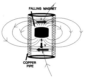
Doc Madhattan: A magnet falling in a metal tube
You have a band of current above and below both opposing the force of gravity on the magnet. Because the currents are in opposite directions they will cancel on axis, not contributing to net BL and not coupled to the coil, thus not correctable through the coil driving circuitry.yes
i*v(t) eddies have two ways of affecting the coil. The first is an opposing force resulting from modulated BL due to eddy currents, which changes the BLi force, which changes velocityacceleration. The change in velocity appears as EMF. The other way is dBL/dt induction causes an EMF proportional to acceleration which as I understand is the one that tends to stop a magnet dead in the air when dropped on a copper plate.proportional to velocity, the magnet stall is Lenz's law.
If I'm right this means the i*v eddies affect voltage drive through both velocity feedback and acceleration feedback (which impersonates an inductance d(i*v(t))/dt). I'm not sure yet to what degree they are corrected by voltage drive or not.they are not. The pickup coil cannot see eddy dissipation directly
It makes sense why you want metal laminations and drilled holes; the laminations prevent off-axis eddies and the holes have the same effect for on-axis eddies (which themselves are coupled to the voicecoil and so potentially correctable).
I've made a crude diagram of the flux circuits and eddies as I understand them.
One thing that keeps tripping me up is the difference between what happens when BL changes and when the BL is physically moving. I have to keep reminding myself that a physically moving BL does not directly cause eddy currents, rather a physically moving BL causes induced voltages, which then produce currents depending on conductivity.
Jn
i*v(t) eddies have two ways of affecting the coil. The first is an opposing force resulting from modulated BL due to eddy currents, which changes the BLi force, which changes velocityacceleration. The change in velocity appears as EMF. The other way is dBL/dt induction causes an EMF proportional to acceleration which as I understand is the one that tends to stop a magnet dead in the air when dropped on a copper plate.proportional to velocity, the magnet stall is Lenz's law.et stall is Lenz's law.
BLi would cause velocity if the cone had no mass and only resistance, a strange assumption on my part. For the model I have to think in more specifics, which results in me changing the underlying assumptions in order to separate the model into more separate parts. What I'm saying is, the inertia of the cone belongs in the physical circuit, not the magnetic circuit, and putting it there would cause me all sorts of trouble. The placement of the inertia in the magnetic circuit is a simplification done for brevity; the model must represent the physical reality without any unnecessary simplifications. So you're right, but maybe you see why I made the mistake.
Lenz's law is a bit unspecific, the Faraday force is F=BLi, not directly related to velocity. The opposing magnetic field generated by Faraday's law depends on the conductivity as without conductivity, no current would flow and no counter force would be generated. It's true that a change in flux produces a counter force, but the conversion from one to the other via conductivity seems to have been omitted and that is a mistake when you need a working model.
In case I need to clarify, by dBL I mean change in flux, not change in inductance.
The dBL/dt induction voltage does represent acceleration as cone velocity generates an eddy current which generates a BL all instantaneously, and then dBL/dt converts it to rate of change of velocity which is acceleration. However the other component of the voltage is Lorenz's law, V=BL*v, which is the familiar back-EMF we all know and love, which does respond to velocity (if dBL/dt responds to velocity, then BL*v must respond to coil position, which is a pleasant thought).
Now when the induction voltage responds to acceleration, the voltage that is produced appears in series with Le, which means that the current re-entering the system responds to velocity, and so results in velocity feedback. So I suspect this is another simplification once made for brevity, but lingering undead as an underlying assumption.
If I'm right this means the i*v eddies affect voltage drive through both velocity feedback and acceleration feedback (which impersonates an inductance d(i*v(t))/dt). I'm not sure yet to what degree they are corrected by voltage drive or not.they are not. The pickup coil cannot see eddy dissipation directly
Okay, true for the magnet in tube type eddies, but I should have indicated I meant a different type of eddy. Lorenz's law says V=BL*v, so when the coil is energized and it is moving, a voltage is generated in the pole piece by the coil BL, the same way a voltage is generated in the coil by the motor BL. This eddy current is coupled to the coil and represents the lossiness of Le. It is not a sub-surface eddy current, although these do exist and they restrict the current to the outer edge of the pole piece AFAIK.
This eddy current causes the acceleration induction voltage effect, while the other eddy currents don't couple to the coil.
Last edited:
Hi,
some choice Christmas present ideas near the end of this page for you all:
Cigarettes and spoons: Christmas gifts from years ago - BBC News
enjoy.
some choice Christmas present ideas near the end of this page for you all:
Cigarettes and spoons: Christmas gifts from years ago - BBC News
enjoy.
BLi would cause velocity if the cone had no mass and only resistance, a strange assumption on my part.BLI is a force which causes acceleration, velocity is the integration of the acceleration. For the model I have to think in more specifics, which results in me changing the underlying assumptions in order to separate the model into more separate parts. What I'm saying is, the inertia of the cone belongs in the physical circuit, not the magnetic circuit, and putting it there would cause me all sorts of trouble.you think that's trouble, try to model the inertial of the air coupling to the cone. It's an unholy combination of motion vectors, air mass, cone angle, dust cap, cabinet order...I would not know where to start.. The placement of the inertia in the magnetic circuit is a simplification done for brevity; the model must represent the physical reality without any unnecessary simplifications. So you're right, but maybe you see why I made the mistake.If this were a simple topic, anybody could do it. They say if you're not making mistakes 50% of the time, it's not R and D..
Lenz's law is a bit unspecificit is very specific in terms of explaining what the system does, but I tend to agree with you that it provides not much in numbers to use as a model. , the Faraday force is F=BLi, not directly related to velocityFaraday's law does not describe a force. It describes the voltage produced for a ring of conductivity surroundinga time varying magnetic flux. The opposing magnetic field generated by Faraday's lawplus Ampere's law depends on the conductivity as without conductivity, no current would flow and no counter force would be generated. It's true that a change in flux produces a counter force, but the conversion from one to the other via conductivity seems to have been omitted and that is a mistake when you need a working model.agreed
In case I need to clarify, by dBL I mean change in flux, not change in inductance.Ah..I use dB/dt to represent time varying flux. perhaps you should use L dB/dt. The problem is, there is simultaneous change in B, and in L.
the following begins to lose clarity, perhaps next year we could put some drawings together to best show what is being discussed.
The dBL/dt induction voltage does represent acceleration as cone velocity generates an eddy current which generates a BL all instantaneously, and then dBL/dt converts it to rate of change of velocity which is acceleration. However the other component of the voltage is Lorenz's law, V=BL*v, which is the familiar back-EMF we all know and love, which does respond to velocity (if dBL/dt responds to velocity, then BL*v must respond to coil position, which is a pleasant thought).
Now when the induction voltage responds to acceleration, the voltage that is produced appears in series with Le, which means that the current re-entering the system responds to velocity, and so results in velocity feedback. So I suspect this is another simplification once made for brevity, but lingering undead as an underlying assumption.
Okay, true for the magnet in tube type eddies, but I should have indicated I meant a different type of eddy. Lorenz's law says V=BL*v, so when the coil is energized and it is moving, a voltage is generated in the pole piece by the coil BL, the same way a voltage is generated in the coil by the motor BL. This eddy current is coupled to the coil and represents the lossiness of Le. It is not a sub-surface eddy current, although these do exist and they restrict the current to the outer edge of the pole piece AFAIK.
This eddy current causes the acceleration induction voltage effect, while the other eddy currents don't couple to the coil.
Happy holidays.
jn
I see, I got mixed up by the Pillonnet et al. paper which states:
F = BL*i = Lorentz or Laplace force
V = BL*v = NOT Faraday's law = ?
EMF = -dB/dt = Faraday's law
Lenz's law = - = the negative sign in Faraday's law
Even Wikipedia doesn't seem to know what BL*v or back-EMF is:
Counter-electromotive force - Wikipedia
It says Lenz's law, but Lenz's law is just a negative sign.
Lenz's law - Wikipedia
I guess we're in 1850 AD again, V=BL*v but no one is trying to explain why. It's just magic.
Happy holidays.
EDIT: Well I finally found it using the keywords "motional EMF":
Faraday's law of induction - Wikipedia
In the very bottom of the Proof section where no one will ever look at it.
So apparently, motional EMF is due to Lorentz force on the individual charges in the wire, and transformer EMF is due to time varying flux.
I was worried I was crazy, unknowingly adding motional EMF and transformer EMF separately to the model just because that was the only way that made sense. I was worried I would have to rework everything.
The coupling between
electrical and mechanical systems is the Faraday force,
Bl×i, and the back electromotive force due to the
Lorentz law, Bl×v.
F = BL*i = Lorentz or Laplace force
V = BL*v = NOT Faraday's law = ?
EMF = -dB/dt = Faraday's law
Lenz's law = - = the negative sign in Faraday's law
Even Wikipedia doesn't seem to know what BL*v or back-EMF is:
Counter-electromotive force - Wikipedia
It says Lenz's law, but Lenz's law is just a negative sign.
Lenz's law - Wikipedia
I guess we're in 1850 AD again, V=BL*v but no one is trying to explain why. It's just magic.
Happy holidays.
EDIT: Well I finally found it using the keywords "motional EMF":
... motional EMF (due to the magnetic Lorentz force on charges by the motion or deformation of the loop in the magnetic field)
Faraday's law of induction - Wikipedia
In the very bottom of the Proof section where no one will ever look at it.
So apparently, motional EMF is due to Lorentz force on the individual charges in the wire, and transformer EMF is due to time varying flux.
I was worried I was crazy, unknowingly adding motional EMF and transformer EMF separately to the model just because that was the only way that made sense. I was worried I would have to rework everything.
Last edited:

What are we going to do to reduce distortion in the driver???
-RNM
Here is a start:
http://www.klippel.de/fileadmin/kli...Diagnosis_and_remedy_of_Nonlinearities_00.pdf
A lot of it has to do with suspension wrangling. With current drive the suspension would have to be redesigned as the solutions given here often have to do with the interplay between suspension and BL(x) and Le(x) which have different effects under current drive. If the driver damping is moved to physical damping rather than electronic, or even no damping and extensive EQ, the considerations change a lot.
Merry Christmas George. Hope the new year is good to you.Merry Christmas
George
I see two significant approaches. Fix the drivers, or figure out where they are at all times. Me, having just a hammer (E/M), choose to attack the driver first.What are we going to do to reduce distortion in the driver???
-RNM
First, toss the conductive former. Aluminum in the gap fights the velocity just as a shock absorber does. Moves easy if pushed slow, but fights harder at high speed. As pure damping, it may somehow be useful, but the second effect I have never seen anybody even think of, is how dragging the conductive surface through the field makes the field lines go to the side. In other words, what we think of as flux lines going straight from pole piece to front plate may be splayed out as a result of the eddies fighting to exclude the field. When they do not go in a straight line, the magnetic lines have to go further to cross the gap. As a result, the coils will see less field and the magnetic structure has less inductance.
This is a velocity modulation of the gap field intensity. If the vc is also carrying a second higher frequency, that will be amplitude modulated by the coil velocity.
This is why I asked if anybody has compared two tone intermodulation between an aluminum former vs nomex in the same magnetic structure.
One way to look for this eddy drag modulation is the setup I have proposed. Make an iron loop with some neos driving the field, a second small gap to place a gauss meter probe, and a third for passing a sheet of aluminum or copper. Moving the plate through the gap should induce eddy currents so the plate will fight to exclude the flux lines from the aluminum, and watch the meter for reduced field in the loop.
A variant I'm considering is to put a disk of spinning aluminum in that gap. That way, I can maintain constant (but variable) dragging velocity. I have a stepper with micro stepping drive at home, I can set an arduino up to pulse the drive.
Also needed is a coil wound around part of the iron loop. That will allow me to measure the inductance of the loop and plot it vs speed of the disc in the gap. That will tell me exactly the impact a former in the gap has on the flux lines in the gap.
The only thing left unknown here is the possibility of the copper wires of the coil eddying sufficiently to have this effect, and if the effect is dependent on the diameter of the vc wire. I envision driving a thin plastic cylinder with the stepper, but lining the cylinder with two layers of copper magnet wire lengths. So, my iron square frame needs the test gap near one of the corners so that the cylinder can go over it into the gap. To reduce this, edge wound VC's reduce the width of the conductors, unfortunately the aspect ratio (height to thickness) means bigger gaps for same gauge.. This can be eliminated by running two, three, or four thin wires in a somewhat bifilar arrangement, and paralleling them outside the gap. Or, figure out how to wind a Litz conductor as a vc wire. Now that is optimum, if not practical..(BTW, that may be another patent lost). Oh well, merry Christmas..😀
Another patent: use one of the individual Litz wires as the pickup coil I previously proposed. Just have the wire vendor color Code one of the strands.
If any speaker manus are reading this, I suspect this is an experiment you should be running. I will drag you guys kicking and screaming into this century tech wise.😀 edit: I see no good reason to accept technological complacency.
Summary: this is a measure of eddy drag modulating the gap field with a conductive former and possibly the copper wire. If the former ends at the coil edge, that is a significant assymetrical effect when the coil is forward (2nd harmonics) and mirror assymetrical as the former is driven into the structure (3rd harmonics).
Jn
Happy holidays to all, sorry for the long post..
Last edited:
Multifilar thin wires or Litz for minimizing eddy currents is a valid proposition.
Ceramic center pole piece and ceramic front plate for minimizing eddy currents is a valid proposition (and it is easier to mass produce compared to radial wise sectioning of steel pole piece and front plate that would be needed for to produce proper lamination)
See also this clever proposed implementation of "iron-less" structure
https://hal.archives-ouvertes.fr/hal-00437000/document
George
It is clever indeed. These structures are consistent with the insertion device magnet structures we use.Multifilar thin wires or Litz for minimizing eddy currents is a valid proposition.
Ceramic center pole piece and ceramic front plate for minimizing eddy currents is a valid proposition (and it is easier to mass produce compared to radial wise sectioning of steel pole piece and front plate that would be needed for to produce proper lamination)
See also this clever proposed implementation of "iron-less" structure
https://hal.archives-ouvertes.fr/hal-00437000/document
George
One question though, why not just use one neo ring instead of three odd shaped ones, and just magnetize it with the proper induction field needed to tailor the final profile. Lots of the magnet volume is wasted using three mag vectors when circular magnetization paths are doable. (That idea is now current practice, sorry). Also, they've designed in an air return path. My idea makes the return gap same as the vc gap and helps contain stray field. Their structure would kill any CRT within ten feet.
Jn
Yah, I know....what's a CRT?😱
Ps..it seems clear that author has never tried to assemble a stack of neos before. You've no idea the type of fixturing required to assemble neo stacks, the forces are just unbelievable. I'd rather build a magnetizer. Does anybody here remember the name Ragnar?
Last edited:
I'm trying to implement the BL curve. But actually it's either the B curve or the L curve, not both at once. From the coil's perspective it is a B curve. From the magnet's perspective it is an L curve.
I realized that until the coil actually begins to leave the gap, the number of turns in the gap are constant. The only thing changing is the number of turns outside the gap. So the modulation must come from these stray turns. Of course an underhung voicecoil must be thought of differently.
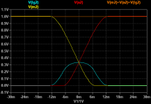
So I can model L as constant, while the proportion of L in different flux loops changes. Attached is a graph for a overhung voicecoil with the gap 1/3rd the thickness of the coil. The number of turns in the gap is never more than 1/3rd of the total L. The curves come from LTspice's smooth limit function, so they are not necessarily realistic, but are an acceptable approximation for now.
Furthermore, I have a theory about Le. I think Le is actually larger outside the motor. After all, the skin depth of steel at 60Hz is in the hundreds of micrometers, acting more like a shorted turn than a magnetic core. We really aren't measuring the inductance of the voicecoil, but rather the inductance of the pole piece. If I'm right, the inductance increases inside the motor because of getting away from the steel and closer to the magnet, and if the Le plot was extended to higher excursion the Le would rise a bit. This also means that possibly motor reluctance could be crudely extracted from the difference in inductance at positive and negative xmax.
I realized that until the coil actually begins to leave the gap, the number of turns in the gap are constant. The only thing changing is the number of turns outside the gap. So the modulation must come from these stray turns. Of course an underhung voicecoil must be thought of differently.
So I can model L as constant, while the proportion of L in different flux loops changes. Attached is a graph for a overhung voicecoil with the gap 1/3rd the thickness of the coil. The number of turns in the gap is never more than 1/3rd of the total L. The curves come from LTspice's smooth limit function, so they are not necessarily realistic, but are an acceptable approximation for now.
Furthermore, I have a theory about Le. I think Le is actually larger outside the motor. After all, the skin depth of steel at 60Hz is in the hundreds of micrometers, acting more like a shorted turn than a magnetic core. We really aren't measuring the inductance of the voicecoil, but rather the inductance of the pole piece. If I'm right, the inductance increases inside the motor because of getting away from the steel and closer to the magnet, and if the Le plot was extended to higher excursion the Le would rise a bit. This also means that possibly motor reluctance could be crudely extracted from the difference in inductance at positive and negative xmax.
Attachments
I'm trying to implement the BL curve. But actually it's either the B curve or the L curve, not both at once. From the coil's perspective it is a B curve. From the magnet's perspective it is an L curve.
I realized that until the coil actually begins to leave the gap, the number of turns in the gap are constant. The only thing changing is the number of turns outside the gap. So the modulation must come from these stray turns. Of course an underhung voicecoil must be thought of differently.yes for the most part.
So I can model L as constant, while the proportion of L in different flux loops changes. Attached is a graph for a overhung voicecoil with the gap 1/3rd the thickness of the coil. The number of turns in the gap is never more than 1/3rd of the total L. The curves come from LTspice's smooth limit function, so they are not necessarily realistic, but are an acceptable approximation for now.
Furthermore, I have a theory about Le. I think Le is actually larger outside the motor. After all, the skin depth of steel at 60Hz is in the hundreds of micrometers, acting more like a shorted turn than a magnetic core. I suspect there's a problem there. Le is smaller without the pole piece as a core.We really aren't measuring the inductance of the voicecoil, but rather the inductance of the pole piece. If I'm right, the inductance increases inside the motor because of getting away from the steel and closer to the magnetmost speakers I see have a steel back plate. It's leaving the gap that is important., and if the Le plot was extended to higher excursion the Le would rise a bit. This also means that possibly motor reluctance could be crudely extracted from the difference in inductance at positive and negative xmax.
But I am really glad you're thinking about the model..
Jn
You must mean Ragnar the driver. He stopped for gas, went inside to pay and drove home. The next day the police stopped by. It seems his car was still at the gas station and another driver of the same make, model and color had left the keys in his car and it was missing.
Your hero? 😉
Your hero? 😉
The other two are there to limit the maximum excursion of the coil magnetically (they are axially magnetized).One question though, why not just use one neo ring instead of three odd shaped ones
Ps..it seems clear that author has never tried to assemble a stack of neos before.
Neos are not mentioned. It can be ceramic magnets. Still a lot of force to counteract while assembling and gluing the magnets together.
I wonder why there hasn’t been any product with such a configuration since 2009.
George
Pole pieces and most magnetic structures are made from compressed powdered metal today. I'm not sure what it's magnetic properties are but they probably aren't the same as solid metal.
The Aura neo structure is mostly Neo and costly. There are patents that describe it.
Flat wire is used to get more copper in the gap. Copper coated aluminium to save weight.
The Aura neo structure is mostly Neo and costly. There are patents that describe it.
Flat wire is used to get more copper in the gap. Copper coated aluminium to save weight.
I have a weird problem with the model. I separated it into 3 flux loops. One loop outside the gap, one loop inside the magnet. The problem is that the portion of the coil in the air generates it's own motional EMF from the B field generated by it's current.
Obviously you don't produce EMF by just waving a coil around in the air, even if it has DC current.
It seems the difference is that when the coil is in the gap, it's field is concentrated and held stationary while the coil moves.
So now this makes me wonder if even the portion of the coil in the gap produces it's own slight field through the permeability of free space, which moves with the coil. This means that if the gap has a permeability of 10, 1 of that is free space and doesn't generate motional EMF whereas the remaining 9 is coming from the gap.
Nope.You must mean Ragnar the driver. He stopped for gas, went inside to pay and drove home. The next day the police stopped by. It seems his car was still at the gas station and another driver of the same make, model and color had left the keys in his car and it was missing.
Your hero? 😉
Think Speakerlab.
Jn
Pole pieces and most magnetic structures are made from compressed powered metal today. I'm not sure what it's magnetic properties are but they probably aren't the same as solid metal.
The Aura neo structure is mostly Neo and costly. There are patents that describe it.
Flat wire is used to get more copper in the gap. Copper coated aluminium to save weight.
Neo is two processes. Sintered, and some kind of plastic matrix. Don't know any details other than sintered was 50 kilotons per year, plastic was 7. Don't know what year the stats were.
Rectangular wire was for packing factor. Round side by side only used 75% of the cross section. They could not utilize hexagonal close packing because the second layer would drop into the interstitials twice per rotation.
When the gap or the magnet dominate the reluctance, it really doesn't matter too much what the steel mu is.
Jn
- Status
- Not open for further replies.
- Home
- Member Areas
- The Lounge
- John Curl's Blowtorch preamplifier part III