He is from 1947, not that old and still alive.Is MH still around? Must be quite an old guy now. I recall he wrote a paper about cable directionality - I'd say that was the real BS.
He's a member of DiyAudio under his own name since 2010, but he never posted anything.
Hans
Last edited:
I think you re talking about what I have called 'AFEC'. Hitachi tried this idea in the early 1980's
[snip]
AFEC is a bit more complex than a straight nested feedback amplifier because you have to null the feedback bridge distortion
[snip]
Augmented Feedback Error Correction (AFEC)
1- Yes, it seems a lof of people had this -quite obvious- same idea.
Which does not detract from the pleasure of having it by oneself and to experience it, is not it? ;-)
2- That is where all the trouble is. Hard to industrialize. Reason why I don't know a commercial product using it on the market ?
Had-you build-it ?
3- Thanks to the link.
He is from 1947, not that old and still alive.
He's a member of DiyAudio under his own name since 2010, be he never posted anything.
Hans
He retired 5 or 6 years ago and iirc now lives in Marrakesh.
Since he was the last in the audio research department at the Essex university, they shut down the department after Malcolm left.
Happens all the time. In The Netherlands we had a Prof who developed the principle of Sound Field Synthesis for large spaces. Was very successful, but the last of the Mohikans there and after he retired they shut down the department.
Jan
The comparison is made substracting the input signal from the output signal reduced to the exact level of the input one. So, little signals, no ?Could you be so kind to explain what you mean with small signal regime and why therefore slew rate should remain unaffected.
And is it good or bad that the slew rate remains unaffected.
For a same slope, slew rate has to be proportional to the level. To equal, let say 20V/µs for a 1V signal, you need at the output of an amp of 29dB gain: 700V/µs. more or less and reciprocally.
Thanks for the circuit. Where is Rg ?
It's not there. You can add it if you'd like. But unity gain operation is a valid mode for CFAs as well as VFAs; operational theories need to deal with it.
Last edited:
I am not sure I understand what you wrote. I fear you misrepresent my thinking once again.CPaul said:But I suspect we can simply add this to the list of things that forr will ignore🙁1) the necessity of Rg and in(-) currents to diminish each other for negative current feedback to occur, which of course means that Rg current cannot flow into in(-). Since he concludes that such a situation rules out current feedback, the inexorable corollary is that negative current feedback is a priori impossible;
I transposed your circuit to the one more familiar to me (modified by adding the Rload and a 100 kOhm resistor between collector and emitter of T1). I could not find an Rg current flowing into in(-) but the current generated by the error voltage flowing from in(-) into Rg.
I am not sure I understand what you wrote. I fear you misrepresent my thinking once again.
I transposed your circuit to the one more familiar to me (modified by adding the Rload and a 100 kOhm resistor between collector and emitter of T1). I could not find an Rg current flowing into in(-) but the current generated by the error voltage flowing from in(-) into Rg.
I cannot be responsible for the changes you made in your circuit. I note you have not identified any flaws in the one I provided, which is all I can address.
You may be unfamiliar with the Hybrid Pi model. OK, consider instead Post 1028. It works with transistors only. It shows that the ratio of the AC signals Ic / Vbe is unequal to gm (1mA/26mV in this case). But if vbe gm were the only thing occurring, then we would see an equality between these terms. Since we don't, there must be another mechanism that explains this. There is - the Early effect, demonstrated by the Hybrid Pi model (for small signal low frequency operation), as well as by the more general Ebers-Moll/Early: ic = Is exp (vbe / VT) ( 1 + Vce/VA ) . If you reject this explanation, how do you explain this obvious inequality?
Half of the emitter/collector transistor current flows from the output through Rf (unity gain) or Rg (non-unity gain), through the resistive Early Effect and terminates in the low Z Current mirror input into which current flows, across which voltages are NOT impressed. The transistor is NOT acting like an ideal voltage-controlled transconductor.
You have said that because the Rf current does not flow into in(-), there is no current feedback. But if the Rf and in(-) currents are to diminish rather than augment one other in non-unity gain circuits, their directions must be such that the Rf current cannot flow into in(-). I have simply added this fact to your assertion to arrive at the obvious implication: negative current feedback is impossible. And I mean by this term the feeding of current to a point in a circuit in which it, not a voltage it creates, causes a change in circuit operation. This excludes the case where a load current is controlled by a VFA - no current is fed anywhere but to ground in such a case.
The comparison is made substracting the input signal from the output signal reduced to the exact level of the input one. So, little signals, no ?
For a same slope, slew rate has to be proportional to the level. To equal, let say 20V/µs for a 1V signal, you need at the output of an amp of 29dB gain: 700V/µs. more or less and reciprocally.
Yes - this is what I mean.
"Is there no error voltage in a CFA ?" is the question.I cannot be responsible for the changes you made in your circuit. I note you have not identified any flaws in the one I provided, which is all I can address.
You may be unfamiliar with the Hybrid Pi model. OK, consider instead Post 1028. It works with transistors only. It shows that the ratio of the AC signals Ic / Vbe is unequal to gm (1mA/26mV in this case). But if vbe gm were the only thing occurring, then we would see an equality between these terms. Since we don't, there must be another mechanism that explains this. There is - the Early effect, demonstrated by the Hybrid Pi model (for small signal low frequency operation), as well as by the more general Ebers-Moll/Early: ic = Is exp (vbe / VT) ( 1 + Vce/VA ) . If you reject this explanation, how do you explain this obvious inequality?
I prefer my circuit to yours because everyting appears much more clear, simple and direct and there is no need to dive in deep calculations (the program does them for the user if any) to establish solid conclusions of the results which can be easily tested in reality with a few components in a few minutes. The circuits I use belong to the general architecture of amplifiers with a single input device input whihc exists since eighty years.I did not see unexpected effects of current flowing into in(+) when adding an Early 100 kOhm resistor between collector and emitter of a single device CFA input.Half of the emitter/collector transistor current flows from the output through Rf (unity gain) or Rg (non-unity gain), through the resistive Early Effect and terminates in the low Z Current mirror input into which current flows, across which voltages are NOT impressed. The transistor is NOT acting like an ideal voltage-controlled transconductor.
You have said that because the Rf current does not flow into in(-), there is no current feedback. But if the Rf and in(-) currents are to diminish rather than augment one other in non-unity gain circuits, their directions must be such that the Rf current cannot flow into in(-). I have simply added this fact to your assertion to arrive at the obvious implication: negative current feedback is impossible. And I mean by this term the feeding of current to a point in a circuit in which it, not a voltage it creates, causes a change in circuit operation. This excludes the case where a load current is controlled by a VFA - no current is fed anywhere but to ground in such a case.
Ir's a bit wondering that texts by various authors writing about CFA do not seem to refer to the Early resistance if it has the importance you said. Or I missed it. Circuits do not know if they are a CFA or a VFA, the physics are the same for all. Note that the authors are generally quite subtle with their conclusions about CFA's. "The designation current feedback is indeed quite appropriate" said Sergio Franco. It means between the lines that it is not a perfect expression, and that a more descriptive and original expression could have been adopted.
"Is there no error voltage in a CFA ?" is the question.
That is NOT the question.
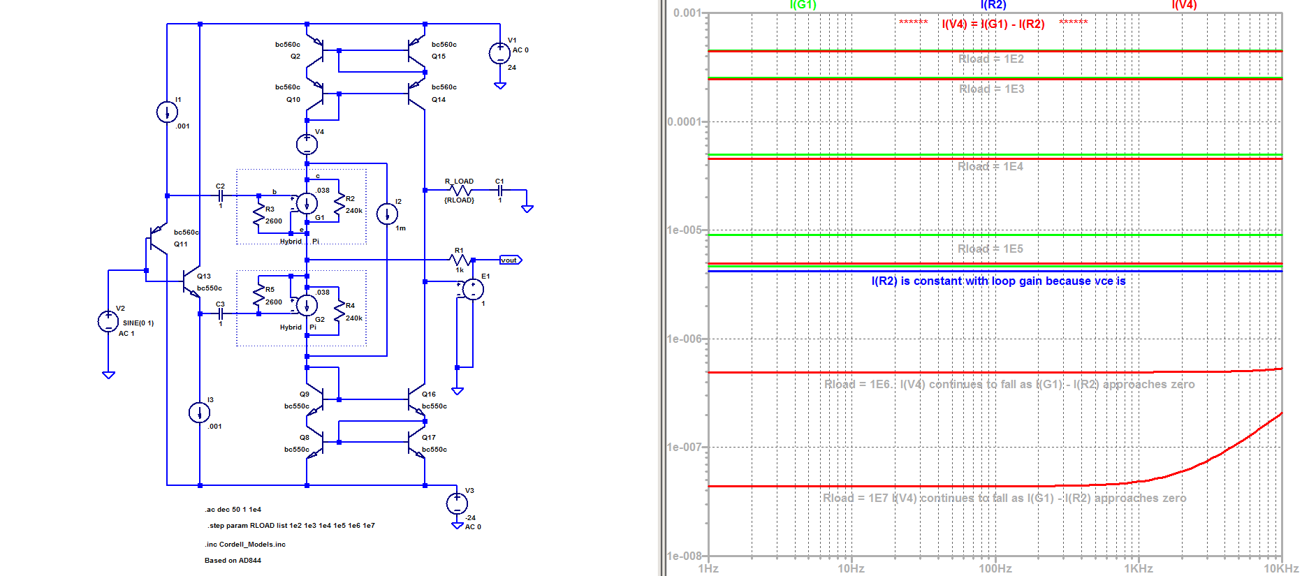
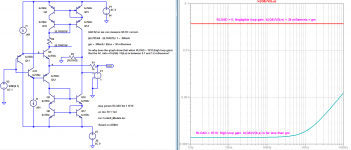
As we might expect and as is shown in the zero feedback case of the attached (RLOAD = 1 ohm), ic/vbe = gm, the transconductance of a transistor (.986mA/26mV in this case.).
But in the high loop gain situation (RLOAD = 1E10 ohms), ic/vbe << gm. HERE is the question: "Why?" The DC collector current hasn't changed, so neither has gm. So why the enormous change in ic/vbe with loop gain?
"Error voltage in the CFA" is no answer - a factor of one one-hundredth of what is expected for ic/vbe is one hell of an error! And the "error" increases WITH loop gain!
I prefer my circuit to yours because everyting appears much more clear, simple and direct...
You can always simplify something to the point that it cannot explain what is happening. Until you can explain the phenomenon of the change in ic/vbe with loop gain, we cannot proceed. Kindly address this observation.
(If you want to run the sim yourself and view the attached graph, you will need to change the extensions of the two .txt files - Cordel_Models.inc and forr.plt.)
Attachments
Half of the emitter/collector transistor current flows from the output through Rf (unity gain) or Rg (non-unity gain), through the resistive Early Effect and terminates in the low Z Current mirror input into which current flows, across which voltages are NOT impressed. The transistor is NOT acting like an ideal voltage-controlled transconductor.
I don't understand.
Early effect is a special case that is not inherent in the topology of CFAs. It can not be an argument to falsify voltage feedback of CFA.
However, I don't see why it is a problem : the Early current is determined by the Vce change caused by the voltage feedback.
Are we now - again - back to the 'the only current I see is the error current' so it can't be current feedback?
Are we now - again - back to a lack of understanding that it is the error current that makes the circuit work, just as in a VFA it is the error voltage between the inputs that makes the circuit work?
Are we now - again - back to a lack of basic knowledge of how a feedback amplifier works??
All this bandwidth wasted and not a iota of progress in understanding.
Jan
It’s turned into a bit of a farce - as Scott said, forr is not for turning.
Science vs dogma 😕
Science vs dogma 😕
As we might expect and as is shown in the zero feedback case of the attached (RLOAD = 1 ohm), ic/vbe = gm, the transconductance of a transistor (.986mA/26mV in this case.).
But in the high loop gain situation (RLOAD = 1E10 ohms), ic/vbe << gm. HERE is the question: "Why?" The DC collector current hasn't changed, so neither has gm. So why the enormous change in ic/vbe with loop gain?
"Error voltage in the CFA" is no answer - a factor of one one-hundredth of what is expected for ic/vbe is one hell of an error! And the "error" increases WITH loop gain!
I think the answer is not so hard.
When open loop gain is low, Vin+ - Vin- is large so the transistor is most driven by Vbe change.
When open loop is high Vin+ - Vin- is low but Vce is the same as previous situation so transistor is most driven by Vce changes.
This is a proof that the transistor is voltage driven.
If the transistor was current driven, there will be no reason the ratio between Gm*Vbe and Vce/Ro change with the open loop gain.
It is only because (Vin+ - Vin-) change with respect to the open loop gain and not Vce the the ratio changes.
Thank you Chris, you give to Forr the proof of what he claims since the beginning of the thread.
Last edited:
It’s turned into a bit of a farce - as Scott said, forr is not for turning.
Science vs dogma 😕
'Building castles in the sky'😎
Jan
I would say : not the question to ask.Originally Posted by forr
"Is there no error voltage in a CFA ?" is the question.
That is NOT the question.
All the defenders of CFA consider the most simple and familiar, one active device input, negative feedback circuits as CFA. This configuration certainly shows what is happening better than more linear but more complex circuits base on the diamond input topology which uses the same principle which could be called unbuffered feedback.You can always simplify something to the point that it cannot explain what is happening.
This is a proof that the transistor is voltage driven.
We all know that we have the choice to consider the transistor as a voltage controlled or current controlled device. Both views can be used in any situation to analyze a circuit with complete correctness.
Decades long designers have selected the most appropriate view depending on which is the easiest to use for analyzing a particular situation.
That you select one particular view as saying anything about a specific topology is astounding, and gives us an interesting view of your reasoning facilities.
You must get a lot of exercise what with all the jumping to conclusions.
Jan
I don't believe that "defenders of CFA" exist as such. The choice between CFA or VFA (by people that knows or master the two topologies) is just a question of preference in audio and simplicity of design.I would say : not the question to ask.
All the defenders of CFA consider the most simple and familiar, one active device input, negative feedback circuits as CFA. This configuration certainly shows what is happening better than more linear but more complex circuits base on the diamond input topology which uses the same principle which could be called buffered feedback.
A CFA is indeed (on my point of view) an amplifier where the signal use a transistor in common emitter and the feedback directly applied to the same transistor working in common base, with no active device adding a pole in the loop and uncorrected distortions in between.
You can do what you want around this return path (a gain block as complex as you like and a power buffer as complex as you like) or outside the loop (Diamond), it will be a CFA. Now, if some use a high impedance in a CFA return path, he just prove he has not understood anything.
The diamond is just used to solve the problem of the VBE (the input voltage has to be the same as the feedback one if you want to avoid any capacitance in the feedback path). The first transistor is outside the loop. A single emitter follower that give the benefit to not add distortion (100% local feedback) and help to minimize the drawbacks of the real input transistor (the second one) by attacking-it in lower impedance.
The preference to CFA or VFA is essentially a question of what some consider as more important in audio: bandwidth and current on demand or distortion and power supply ripple rejection. And you are free to improve to your best the drawbacks of each topology.
In a way, it is like to prefer the use of inverting mode in an vfa OPA VS the positive one. And I wonder why this don't lead at such a strange controversy about CFAs.
This said, this thread had bring the advantage that the VFA topology has been analysed here in all their aspects.
Please, Forr, stop this endless question about currents and voltages, you have to look at the both aspects, as their are, as Jan just said, two points of view one an unique phenomena: the ways electrons flows in a particular point.
Last edited:
- Home
- Amplifiers
- Solid State
- Current Feedback Amplifiers, not only a semantic problem?