Don't you have a humor measurement device in your LAB that will haunt my nights ?
Nope, my sense of humor doesn't have an electrical metric.
Do not leave industry dictate its science, we now know how it costs to the planet. Inform involved people of the incongruities !
Attached image : I think the author is John Curl.
I would not be concerned about that, but then I'm not exactly the "save the planet" type.
Yep, a JC pre-1982 CFA. Nobody (including himself, his cronies and his reviewers) cared to call this a CFA.
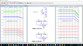
Just to illustrate why I like CFA, one of theamplifiers of mine that I prefer for Medium/high frequencies. A little basic CFA, with Diamond input, simple VAS and mosfet power devices.
Rock stable as you can see.
Harmonic distortion is -100dB at 1KHz, and -80dB at 20kHz. (when I say that actual devices are not fast enough ;-)
Thank to Fletcher et Munson to allow-me to sleep by night.
Of course, all input and output passive filters removed to impress the audience.
And i will keep the slew rate value for the marketing department ;-)
Professor, that simulation looks good! Did you actually build this? Do you have measurements?
Jan
Professor, that simulation looks good! Did you actually build this? Do you have measurements?
15MHz ULGF in a power amplifier, if implemented, this must be a new world record. I've build once a 8MHz ULGF MOSFET amplifier, measured it, but it never made it beyond a PCB prototype. Too hard to manage all the details, even the power supply wiring placement was changing the stability margins. But then, I'm only an amateur 😀.
Yes, for the full 100%.
Thank you for helping to sharpen the definitions.
Hans
Hooray for us! We conquered miscommunications, disagreements, and I suspect both learned something. And wonder of wonders, mirbile dictu, we had not a discouraging word to say to one another!
Happy Holidays, Hans.
Same for you, ChrisHooray for us! We conquered miscommunications, disagreements, and I suspect both learned something. And wonder of wonders, mirbile dictu, we had not a discouraging word to say to one another!
Happy Holidays, Hans.

Yes at the first question. No at the second one.Professor, that simulation looks good! Did you actually build this? Do you have measurements?
Since i'm retired, I no more have measurements instruments that goes that high and allowed me to send Tintin on the moon.
Of course on the bench, It needed some little adjustments and performed a little less impressive. Especially since, in real life, it is equipped with a 12db/oct low-pass filter in the diamond around 200KHz ;-)
And, yes, a lot of work near the power supplies lines, the feedback lines, and the general physical implementation. SMD helps.
Anyway, as long as my amp is fast enough (and, oh lord, it is) and stable, with near perfect square waves at 50KHz, I consider the job done on a technical point of view.
And as long as it sounds nice (no listening fatigue, good separation between instruments, micro dynamic details and no audible noise or distortion), I'm happy.
I do not published this to show my guts, but as a proof of CFA's advantages in regard to the ease of stability with extended bandwidths.
And to give to those that had not tried this topology the curiosity to try by themselves (it is fun).
Oh, BTW, don't ask-me the schematic, I have sell-it to a company and now, I'm under a non disclosure agreement :-(
They are several threads in this forum instructing enough about CFAs, I believe, Jan, that you know them all:
Slewmaster - CFA vs. VFA "Rumble"
Simple Symetrical Amplifier, VSSA Lateral MosFet Amplifier, TSSA - The Simplest Symmetrical Amplifier .
200W MOSFET CFA amp .
And you know the gurus of this religion: Ostripper, Lazycat, Dadod, Bonsai (sorry for the forgotten other ones).
And, of course, Scott Wurser who watches the class under an iron discipline
and John Curl, when he don't smoke some Bybee device ;-)
Last edited:
I once asked Barrie Gilbert (ahum) why there were not more current conveyors like the AD844 and the (now obsolete) AD846 that had the Tz node brought out. That would make it so much more flexible!
His answer was that the few extra parasitic pF that the physical connection to an external pin causes would severely limit the hf performance.
Jan
Barrie Gilbert is thought a brilliant designer. His answer is consistant with CFA's being used in the conventional sense as a whole. This is evidenced in that no applications exist in the data sheets of any alternative advantages to bringing out the Tz node.
The diagram attached is a simplified connection using the Tz node in what can be described as feedforward current to the inverting terminal as the output. Although the Tz node could be grounded, in being returned it eliminates grounding, doubles the drive current and effectively halves the input buffers output impedance. In so doing the 3 MegOhm Tz resistance becomes paralleled across the 50 Ohm source impedance of the input buffer. The reduction in Tz node resistance drastically reduces the effects of capacitances at the Tz node, as nullifying the object of Barrie Gilbert's concerns.
The return from the Tz node increases bandwidth and particularly stability, as no longer passing through two further stages in the diamond before returning to the inverting terminal. Unlike the output buffer the input buffer requires considerably higher standards of linearity for reasons being uncorrectable references. This manner of output is considered more of an ultra simplistic, laser offset trimmed unity gain reference buffer connectable to improved networks to what normally follows thereafter in a CFA.
As one example, it seems possible to be used as an alternative to networks discussed with JPaul and I to minimize non-linear input capacitances in the measurement of tube amplifier parameters. Ultimately the concept is just to create a stable environment around the AD844's pins as if nothing was changing around them. This means unloading the output from pin 2 and pin 5 by connection to the high impedance input of the LT...., and tracking the power supply pins of the AD844 to the voltage on the input terminal. The intent is to null out the capacitances to the power supply pins for increased bandwidth with high source resistance like 100K Ohm.
Attachments
Same for you, Chris
Hi again, Hans. As I mentioned, I wanted to consider the assumptions and limits (even the absurd ones) of your proposed test. I've selected a 400MHz VFA and a 400MHz CFA. I draw no conclusions, make no proposals, and have no hidden agenda. I simply present some data and am interested in your thoughts.
The first thing I wanted to do was to vary the shunt resistor in your test more than the 500 and 5000 ohms that you used. The more I thought about it, the more I decided I didn't need it. Because of the 1 Farad capacitor, I could simply vary the resistors in the T network.
The attached looks at not only the output voltages, but also the inverting input currents which, considering the 1V non-inverting input, can be thought of as conductances.
Again, no agenda on my part. Just interested in your thoughts about the results.
Attachments
As one example, it seems possible to be used as an alternative
Hah! If you want weird uses for the AD844, try to parse this! 😀
Output stage of my paX amp.
Jan
Attachments

Nice Jan.
When the discussion on HEC was in full swing a few years ago, I did a circuit using a high speed opamp to do the job of the transistors in MH’s original concept. The results in simulation were very promising. IIRC I used one of LT’s high speed video opamps from the device library in LTspice.
When the discussion on HEC was in full swing a few years ago, I did a circuit using a high speed opamp to do the job of the transistors in MH’s original concept. The results in simulation were very promising. IIRC I used one of LT’s high speed video opamps from the device library in LTspice.
Yes. The circuit around the AD844 is in concept (and execution) very simple, straightforward, but almost nobody sees it because it is so unusual. When explained, they all say - but of course! 😎
And of course if your mindset is in denial of current feedback, no way you are going to understand it!
Jan
And of course if your mindset is in denial of current feedback, no way you are going to understand it!
Jan
Hi all, finally managed to catch up with this interesting read.
So, in a classic VFA power amplifier the output signal is fed back to the base of an LPT via high value resistors. The current needed to feed the base of the LPT is minute or none existing if jfet. So the vbe is by far the dominant factor in this case.
In a classic cfa power amplifier, the output signal is fed back to the emitter of the input transistor, be it a single ended or diamond buffer, via low value resistors, rf & rg. So here we have a large current flowing from (to) output, through feedback resistors, through the emitter/collector of the input transistor, feeding the vas/tis with whatever current required. Of course there is the vbe of the input transistor in play as well, but in this case the current through the complete feedback loop is by far the dominant factor. So with all this current flowing through the feedback loop, why not just call this a current feedback amplifier?
Hi Jan,Hah! If you want weird uses for the AD844, try to parse this! 😀
Output stage of my paX amp.
Jan
Maybe I'm overlooking something, but this amp has only a gain of 0dB or was this the intention ?
The connection from In+ to Tz is quite clever in keeping the whole circuit stable.
Hans
Hi Jan,
Maybe I'm overlooking something, but this amp has only a gain of 0dB or was this the intention ?
The connection from In+ to Tz is quite clever in keeping the whole circuit stable.
Hans
Yes gain of one output stage, that's also what the caption says ;-)
Actually that connection is positive feedback and does not help stability. The pos feedback at hf is decreased by the C3 across R25 to aid stability.
The way this works is that the difference between the + input and the amp output sets up an error current in R34. That error current comes out of pin 5 Tz (due to the current feedback operation ;-) and sets up an identical correction voltage across R25 which is added to Vdrive, the input voltage. This is the HEC error correction, and (with ideal and perfect matched resistors ) fully nulls the output error.
Jan
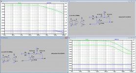
Hi Chris,Hi again, Hans. As I mentioned, I wanted to consider the assumptions and limits (even the absurd ones) of your proposed test. I've selected a 400MHz VFA and a 400MHz CFA. I draw no conclusions, make no proposals, and have no hidden agenda. I simply present some data and am interested in your thoughts.
The first thing I wanted to do was to vary the shunt resistor in your test more than the 500 and 5000 ohms that you used. The more I thought about it, the more I decided I didn't need it. Because of the 1 Farad capacitor, I could simply vary the resistors in the T network.
The attached looks at not only the output voltages, but also the inverting input currents which, considering the 1V non-inverting input, can be thought of as conductances.
Again, no agenda on my part. Just interested in your thoughts about the results.
Sorry, but I did't really get what you tried to achieve.
The idea behind test my set up was that only the topology of a CFA makes that varying Rg in an open loop circuit wil vary the output voltage.
For that I have chosen practical values for Rg being resp. 500 Ohm and 5K.
The 1Gig feedback resistors for AC plus 1F in between can be regarded as open loop and only serve to zero the DC output voltage.
See my simulations for the same parts as you were using.
Quite convincing to my opinion, or is there still anything you are missing ?
Hans
Attachments
Yes gain of one output stage, that's also what the caption says ;-)
Actually that connection is positive feedback and does not help stability. The pos feedback at hf is decreased by the C3 across R25 to aid stability.
The way this works is that the difference between the + input and the amp output sets up an error current in R34. That error current comes out of pin 5 Tz (due to the current feedback operation ;-) and sets up an identical correction voltage across R25 which is added to Vdrive, the input voltage. This is the HEC error correction, and (with ideal and perfect matched resistors ) fully nulls the output error.
Jan
Clever idea Jan.
However remove the connection from Tz and you have an oscillator that can only be killed with a cap on Tz, thereby significantly reducing the BW.
Hans
Yes gain of one output stage, that's also what the caption says ;-)
Jan
So in fact you have separated the voltage amp from the current amp, just like I did, true ?
Hans
Hi Chris,
Sorry, but I did't really get what you tried to achieve.
Hans
Hans, what I posted was a simpler circuit (one less resistor). I also varied the resistor values over a wider range to test the limits of the idea. It was easy to look at both output voltage and input current, so I did. The results still allow you to distinguish between VFAs and CFAs.
- Home
- Amplifiers
- Solid State
- Current Feedback Amplifiers, not only a semantic problem?