I don't understand.
Early effect is a special case that is not inherent in the topology of CFAs. It can not be an argument to falsify voltage feedback of CFA.
The justification for your assertion is missing.
However, I don't see why it is a problem : the Early current is determined by the Vce change caused by the voltage feedback.
Now you must assemble a Ptolemaic explanation to describe a simple Copernican system.
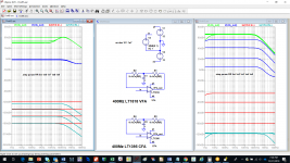
Please tell me what you disagree with in the following screen shot:
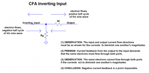
The consequence of your premise is clear: it assumes your preferred conclusion! Your premise is disputed by applying conservation of charge at in (-) and writing the appropriate equation to establish the mutually diminishing interaction of the output and input currents: in (-) = I(Rg) - I(Rf). Clearly, the output current affects the input current and the collector current itself in the prescribed, simple manner.
(1) To describe the transistor as operating as a voltage controlled current source only is false. A more complex description is required.
(2) Regardless of loop gain, almost all of the current flowing through the emitter at in (-) always flows through the collector, and into the low impedance input of a current mirror.
Finally, please explain how, when global AC feedback is removed and an excitation is applied to the inputs of a 400MHz VFA and a 400MHz CFA in a test developed by Hans Polak and modified by me, the responses of the circuits can be so different if they both operate employing the same type of feedback?
Attachments

I think the answer is not so hard.
When open loop gain is low, Vin+ - Vin- is large so the transistor is most driven by Vbe change.
When open loop is high Vin+ - Vin- is low but Vce is the same as previous situation so transistor is most driven by Vce changes.
You get it! But you do realize that up until now, we were living with "the transistor is a perfect transconductor paradigm"? The previous understanding was simply wrong. It most obviously is not - it's also a simple resistor.
Realize also that this analysis poses no danger to the current feedback paradigm: the collector current, which controls the output, is still virtually identical to the current entering in (-). Such a simple explanation - contrast it with the complexity of the explanation now required to support the voltage paradigm - Ptolemy when Copernicus would suffice.
This is a proof that the transistor is voltage driven.
A current travels through ro. ro terminates in a low impedance current mirror input, almost AC ground. Of course there will be a voltage across ro! Were there not, Ohm's Law would be violated!
I do believe that your way of looking at this circuit requires us to conclude that current feedback is impossible, simply because there's always a voltage involved.
I would say : not the question to ask.
All the defenders of CFA consider the most simple and familiar, one active device input, negative feedback circuits as CFA. This configuration certainly shows what is happening better than more linear but more complex circuits base on the diamond input topology which uses the same principle which could be called unbuffered feedback.
I don't understand.
I wonder how some (younger generation ?) dread "electricity" and one of his children: "electronic".
I was taught its rudiments with analogies with hydraulic. Flows and pressures.
Sometimes, I wonder if some has no "feelings" of what happens in a circuit, and if they just apply blind totally abstract formulas. Or, worse, if they leave simulators to feel (and listen) in their own place ;-)
I was taught its rudiments with analogies with hydraulic. Flows and pressures.
Sometimes, I wonder if some has no "feelings" of what happens in a circuit, and if they just apply blind totally abstract formulas. Or, worse, if they leave simulators to feel (and listen) in their own place ;-)
Last edited:
I wonder how some (younger generation ?) dread "electricity" and one of his children: "electronic".
I was taught its rudiments with analogies with hydraulic. Flows and pressures.
Sometimes, I wonder if some has no "feelings" of what happens in a circuit, and if they just apply blind totally abstract formulas. Or, worse, if they leave simulators to feel (and listen) in their own place ;-)
I know that it took me a while to develop a "feeling" for circuits. I remember at one time "feeling" that there was no necessary connection between the impedances of a given two-terminal port when it was employed first as an input and next as an output.
Years later, back in the day when we conversed by letter, I remember arguing with someone who claimed that "output impedance" was just that of the "generator" and any component that delivered power to it; the impedance of coupling capacitors and DC-establishing resistors had to be removed from consideration if "output impedance" were to be determined.
I had about the same luck as I am having here in convincing him otherwise.
🙂IYears later, back in the day when we conversed by letter, I remember arguing with someone who claimed that "output impedance" was just that of the "generator" and any component that delivered power to it; the impedance of coupling capacitors and DC-establishing resistors had to be removed from consideration if "output impedance" were to be determined.
I had about the same luck as I am having here in convincing him otherwise.
To continue with my hydraulic comparison, I recently had to work on the automatic gearbox of my car. Looking at the valve body, I surprised myself to try to imagine an electronic equivalent schematic to understand how it works.
About convincing people, why ?
If I like to exchange with people about electronic, it is because, sometimes, i discover a particular aspect that i was not aware of. Or a clever idea on how to organise a party with them.
Electronic devices are complex buddies and we often neglect one aspect of their "personality". Different images that other people can have of their characters help to use them in a more friendly and efficient way, knowing them better.
So, if, sometimes, I give a personal point of view (that I try to keep as simple as possible), it is in this kind of spirit.
If somebody has a definite point of view, often "religious", he will not learn anything, so you have no luck to convince him. HE is the one that loose something. and you had done your best to bring-him a gift.
This thread is a good example of how different can be our ways to understand or "feel" electronic. And how we can all be stuck in our own certainties and personal character, have different and even opposite approaches.
I have the same deep respect and affection, by example, to John Curl and Scott Wurcer. Both had produced dawn good products. One with an approach mainly based on feelings, close to "magic" (can be BYBEE crazy sometimes ;-) with a lot of listening, the other with a deep scientific approach (can be robotic sometimes).
As always I think the best way is in the middle. Pity they dont takes their holidays together ;-)
Last edited:
???The justification for your assertion is missing.
Please, Chris, I found my glasses, it is not necessary to insert pics larger than my screen.
I am not sure of being the right recipient of your beautiful drawing with beautiful arrows.Now you must assemble a Ptolemaic explanation to describe a simple Copernican system......
Sure. I take your : Ic = Gm*Vbe + Vce/Ro which corresponds exactly to a current source controlled by voltages.(1) To describe the transistor as operating as a voltage controlled current source only is false. A more complex description is required.
You mean emitter current of a npn transistor comes from the collector ? very original theory.(2) Regardless of loop gain, almost all of the current flowing through the emitter at in (-) always flows through the collector, and into the low impedance input of a current mirror.
The low impedance current mirror is a specific case.
You would ask to circuit designer.Finally, please explain how, when global AC feedback is removed and an excitation is applied to the inputs of a 400MHz VFA and a 400MHz CFA in a test developed by Hans Polak and modified by me, the responses of the circuits can be so different if they both operate employing the same type of feedback?
You get it! But you do realize that up until now, we were living with "the transistor is a perfect transconductor paradigm"? The previous understanding was simply wrong. It most obviously is not - it's also a simple resistor.
Realize also that this analysis poses no danger to the current feedback paradigm: the collector current, which controls the output, is still virtually identical to the current entering in (-). Such a simple explanation - contrast it with the complexity of the explanation now required to support the voltage paradigm - Ptolemy when Copernicus would suffice.
A current travels through ro. ro terminates in a low impedance current mirror input, almost AC ground. Of course there will be a voltage across ro! Were there not, Ohm's Law would be violated!
I do believe that your way of looking at this circuit requires us to conclude that current feedback is impossible, simply because there's always a voltage involved.
Current feedback don't explain why CFA is driven by Vbe on low open loop gain and by Vce on high open loop gain.
voltage feedback does.
The design of amplifiers using the current gain of bipolar transistors is a challenge. Readers of Linear Audio and british Electronics World know some authors who tried it (Ian Hegglun Wim de Jager,van Tuy & van der Ven), feeding the bases under high impedance . The voltage control aspect of bipolar transistors is not excluded when analyzing their circuits.We all know that we have the choice to consider the transistor as a voltage controlled or current controlled device. Both views can be used in any situation to analyze a circuit with complete correctness.
Decades long designers have selected the most appropriate view depending on which is the easiest to use for analyzing a particular situation.
That you select one particular view as saying anything about a specific topology is astounding, and gives us an interesting view of your reasoning facilities. You must get a lot of exercise what with all the jumping to conclusions. Jan
But all this has nothing to do with current feedback. Because :
1. CFA's are not an application specific to bipolar transistors, many are built with FET's or tubes.
2. bipolar CFA's, despite what the naming could suggest, rely on the transconductance of the transistors, not on their current gain.
The distinction between VFA and CFA is that, in VFA the feedback voltage defined by a resistive divider which is buffered by a voltage follower, as in VFA, it is apparently not (yes, there is voltage feedback in a CFA).I don't understand.
A very short lesson to manipulate images :Please, Chris, I found my glasses, it is not necessary to insert pics larger than my screen
https://www.diyaudio.com/forums/sol...dback-amplifiers-semantic-45.html#post5608860.
FastStone Resizer is free. I use the four Faststone products (two need a licence) every day. They provide a huge time saving.
The consequence of your premise is clear: it assumes your preferred conclusion! Your premise is disputed by applying conservation of charge at in (-) and writing the appropriate equation to establish the mutually diminishing interaction of the output and input currents: in (-) = I(Rg) - I(Rf). Clearly, the output current affects the input current and the collector current itself in the prescribed, simple manner.
What controls I(Rf) and the whole loop is too often forgotten.(2) Regardless of loop gain, almost all of the current flowing through the emitter at in (-) always flows through the collector, and into the low impedance input of a current mirror.
Not false, incomplete. But sufficient to analyze most circuits.(1) To describe the transistor as operating as a voltage controlled current source only is false.
CFA's can rely on active devices which are closer to voltage controlled current sources than bipolars. Weak argument.
Audio amplfiers having 400 MHz bandwidth, our friend Tournesol will be the happiest man of the audio community.Finally, please explain how, when global AC feedback is removed and an excitation is applied to the inputs of a 400MHz VFA and a 400MHz CFA in a test developed by Hans Polak and modified by me, the responses of the circuits can be so different if they both operate employing the same type of feedback?
2. bipolar CFA's, despite what the naming could suggest, rely on the transconductance of the transistors, not on their current gain.
According to Wikipedia:The distinction between VFA and CFA is that, in VFA the feedback voltage defined by a resistive divider which is buffered by a voltage follower, as in VFA, it is apparently not (yes, there is voltage feedback in a CFA).
Transconductance (for transfer conductance), also infrequently called mutual conductance, is the electrical characteristic relating the current through the output of a device to the voltage across the input of a device.
So, you can consider that, in a LTP, the voltage of the +input drive the *current* in its emitter resistance, and that the voltage on the - input feedback transistor affect the same *current* in inverse.
Are-you concluding a VFA is a current feedback amplifier with a buffered current feedback signal ?
Please, can't you stop this crazy game, turning round and round ?
Last edited:
How clever a comeback to use as an excuse to avoid answering the question. Here's a second chance; I hope you won't duck it again.I am not sure of being the right recipient of your beautiful drawing with beautiful arrows.
Sure. I take your : Ic = Gm*Vbe + Vce/Ro which corresponds exactly to a current source controlled by voltages.
So there is no distinction between current sources and resistors? Wow!
Remember, I have never claimed that there is not a relationship between voltages and currents. You're fighting a straw man. It is you and forr who are claiming that there is no feedback of current even though Ic is approximately Ie, and Ie is equal to a simple difference between the Rg and the output stage currents.
You mean emitter current of a npn transistor comes from the collector ? very original theory.
How do you get this from "almost all of the current flowing through the emitter at in (-) always flows through the collector"? Original indeed! There is nothing in that phrase that references current origins.
The low impedance current mirror is a specific case.
???
So specific that it's the termination of the input stage collector of just about every CFA IC ever made? And even though only small voltage changes appear across the mirror input, this is still an example of voltage feedback because there's a voltage on the other side of ro?
You would ask to circuit designer.
Oh, come on! Don't hide behind that canard! If the VFA didn't need DC feedback to avoid railing the output, the circuit could have simply involved the source, R2 and the op amps! You need help understanding something as simple as that?
The most likely reason for your reply is that you can't explain why two identical types of input stage feedback could yield such different results. Here's a second chance again.
Avoiding inconvenient challenges casts aspersions on the positions being taken.
Not false, incomplete. But sufficient to analyze most circuits.
Yes, clearly quite incomplete. Obviously insufficient to analyze a CFA in any detail.[/QUOTE]
CFA's can rely on active devices which are closer to voltage controlled current sources than bipolars. Weak argument.
I don't understand your assertion.
Audio amplfiers having 400 MHz bandwidth, our friend Tournesol will be the happiest man of the audio community.
Nothing special about 400MHz; just wanted similar bw's for the CFA and VFA,
The first part of the claim is attached. The next part follows:
And here's the reply:
The reply is obviously not an answer; you avoided the question.
Your premise that current feedback demands that some portion of the output stage current must also flow in the input stage inexorably leads to the conclusion that negative current feedback is impossible.
And oh, yes, and then there's the question of why two circuits, deprived of AC feedback, with supposedly identical types of input stage feedback, have such obviously different responses. No answer there either.
Originally Posted by CPaul
The consequence of your premise is clear: it assumes your preferred conclusion! Your premise is disputed by applying conservation of charge at in (-) and writing the appropriate equation to establish the mutually diminishing interaction of the output and input currents: in (-) = I(Rg) - I(Rf). Clearly, the output current affects the input current and the collector current itself in the prescribed, simple manner.
The consequence of your premise is clear: it assumes your preferred conclusion! Your premise is disputed by applying conservation of charge at in (-) and writing the appropriate equation to establish the mutually diminishing interaction of the output and input currents: in (-) = I(Rg) - I(Rf). Clearly, the output current affects the input current and the collector current itself in the prescribed, simple manner.
And here's the reply:
What controls I(Rf) and the whole loop is too often forgotten.
The reply is obviously not an answer; you avoided the question.
Your premise that current feedback demands that some portion of the output stage current must also flow in the input stage inexorably leads to the conclusion that negative current feedback is impossible.
And oh, yes, and then there's the question of why two circuits, deprived of AC feedback, with supposedly identical types of input stage feedback, have such obviously different responses. No answer there either.
Attachments
Last edited:
You may be unfamiliar with the Hybrid Pi model. OK, consider instead Post 1028. It works with transistors only. It shows that the ratio of the AC signals Ic / Vbe is unequal to gm (1mA/26mV in this case). But if vbe gm were the only thing occurring, then we would see an equality between these terms. Since we don't, there must be another mechanism that explains this. There is - the Early effect, demonstrated by the Hybrid Pi model (for small signal low frequency operation), as well as by the more general Ebers-Moll/Early: ic = Is exp (vbe / VT) ( 1 + Vce/VA ) . If you reject this explanation, how do you explain this obvious inequality?
Half of the emitter/collector transistor current flows from the output through Rf (unity gain) or Rg (non-unity gain), through the resistive Early Effect and terminates in the low Z Current mirror input into which current flows, across which voltages are NOT impressed. The transistor is NOT acting like an ideal voltage-controlled transconductor.
You have said that because the Rf current does not flow into in(-), there is no current feedback. But if the Rf and in(-) currents are to diminish rather than augment one other in non-unity gain circuits, their directions must be such that the Rf current cannot flow into in(-). I have simply added this fact to your assertion to arrive at the obvious implication: negative current feedback is impossible. And I mean by this term the feeding of current to a point in a circuit in which it, not a voltage it creates, causes a change in circuit operation. This excludes the case where a load current is controlled by a VFA - no current is fed anywhere but to ground in such a case.
Chris, I would apologize for me being rather slow, but could you summarize in two lines your position regarding the CFA topology?
As slow as I am, I detected in the above prose some serious confusions regarding small signal vs. large signal analysis. From a small signal analysis perspective, you certainly cannot draw the conclusion that gm is modulated by any current in the circuit, since such a conclusion would directly collide with the small signal analysis premises (operating voltages and currents are constant). The Early voltage (and hence ro) is also constant for the purpose of a small signal analysis, and the whole and each and every portion of the circuit is considered precisely linear and time invariant.
A larger signal analysis (aka "transient" in Spice) could show such modulation effects, but then gm is not well defined for large signal to start with; see an oscillator amplitude calculation problem, a large signal Gm is used, but only as a starting point for an iterative process. This Gm value has in common with the small signal gm=Ic/(kT/q) only the mA/V dimension. There are also multiple sources that could modulate Gm, Ebers Moll covers a few. For an even more accurate description, you would need to go down to the Boltzmann transport equation that governs the charge transport in condensed matter (in particular a BJT), something not for the faint hearts.
And finally, you seem to infer (sorry if my understanding is wrong) than only BJTs are supporting "CFA" which is definitely incorrect. A CFA (with it's remarkable large and small signal properties) can be implemented with JFETs, MOSFETs or tubes. Even if a CFA would require changing the BJT as a Voltage Controlled Current Source view to something else, that would really be a challenge to consider for a MOSFET, tube or JFET CFA.
Last edited:
Chris, I would apologize for me being rather slow, but could you summarize in two lines your position regarding the CFA topology?
Hi Syn08, welcome to the discussion! Please forgive me if I reply to this request by listing some things I did NOT mean to imply.
As slow as I am, I detected in the above prose some serious confusions regarding small signal vs. large signal analysis. From a small signal analysis perspective, you certainly cannot draw the conclusion that gm is modulated by any current in the circuit, since such a conclusion would directly collide with the small signal analysis premises (operating voltages and currents are constant). The Early voltage (and hence ro) is also constant for the purpose of a small signal analysis, and the whole and each and every portion of the circuit is considered precisely linear and time invariant.
A larger signal analysis (aka "transient" in Spice) could show such modulation effects, but then gm is not well defined for large signal to start with; see an oscillator amplitude calculation problem, a large signal Gm is used, but only as a starting point for an iterative process. This Gm value has in common with the small signal gm=Ic/(kT/q) only the mA/V dimension. There are also multiple sources that could modulate Gm, Ebers Moll covers a few.
Agree completely. Perhaps you can tell me what I wrote that suggested that I was considering a modulation of gm or ro. I certainly did not intend that! It's nice to see someone else using the same terms as I. I remember well the distinction between gm and Gm, for instance.
For an even more accurate description, you would need to go down to the Boltzmann transport equation that governs the charge transport in condensed matter (in particular a BJT), something not for the faint hearts.
And my heart would be among those faint ones!
And finally, you seem to infer (sorry if my understanding is wrong) than only BJTs are supporting "CFA" which is definitely incorrect. A CFA (with it's remarkable large and small signal properties) can be implemented with JFETs, MOSFETs or tubes.
I do not infer or wish to imply that only BJTs can make CFAs , but I agree that my comments were limited to BJTs. That should not be construed as meaning that I believe that you can't make them with these other devices.
Even if a CFA would require changing the BJT as a Voltage Controlled Current Source view to something else, that would really be a challenge to consider for a MOSFET, tube or JFET CFA.
Now you've lost me, but I am intrigued. Why do you say this, and would you care to elaborate?
The purpose of this thread has never been to analyze CFA's in detail.Originally Posted by forr
Not false, incomplete. But sufficient to analyze most circuits.
CPaul > Yes, clearly quite incomplete. Obviously insufficient to analyze a CFA in any detail.
Syn08 answered for me in advance :Originally Posted by forr
CPaul > I don't understand your assertion.
Syn08 > And finally, you seem to infer (sorry if my understanding is wrong) than only BJTs are supporting "CFA" which is definitely incorrect. A CFA (with it's remarkable large and small signal properties) can be implemented with JFETs, MOSFETs or tubes. Even if a CFA would require changing the BJT as a Voltage Controlled Current Source view to something else, that would really be a challenge to consider for a MOSFET, tube or JFET CFA.
A walk well outside of our garden, then.CPaul > Nothing special about 400MHz; just wanted similar bw's for the CFA and VFA,
Last edited:
I don't understand.How clever a comeback to use as an excuse to avoid answering the question. Here's a second chance; I hope you won't duck it again.
You understand what you can.So there is no distinction between current sources and resistors? Wow!
I just wrote I = V/R. you connect a resistor on a voltage source, and you have current.
Yes, I demonstrate it is a voltage feedback.Remember, I have never claimed that there is not a relationship between voltages and currents. You're fighting a straw man. It is you and forr who are claiming that there is no feedback of current even though Ic is approximately Ie, and Ie is equal to a simple difference between the Rg and the output stage currents.
How do you get this from "almost all of the current flowing through the emitter at in (-) always flows through the collector"? Original indeed! There is nothing in that phrase that references current origins.
May be still my poor english, but you say that emitter current flows through collector, no ?
No.So specific that it's the termination of the input stage collector of just about every CFA IC ever made?
Two identical types of input stage ?Oh, come on! Don't hide behind that canard! If the VFA didn't need DC feedback to avoid railing the output, the circuit could have simply involved the source, R2 and the op amps! You need help understanding something as simple as that?
The most likely reason for your reply is that you can't explain why two identical types of input stage feedback could yield such different results. Here's a second chance again.
I don't understand.
- Home
- Amplifiers
- Solid State
- Current Feedback Amplifiers, not only a semantic problem?