It shows that the ratio of the AC signals Ic / Vbe is unequal to gm (1mA/26mV in this case).
I can't really follow how you drew this conclusion, but it is certainly wrong for a small signal analysis. If you think of a large signal analysis, then the transconductance is modified by many factors, at any moment in time, so I don't know how you would isolate a particular contribution. Sorry, I'm not a LTSpice camper, so I can't help interpreting the results straight from the simulator output.
But if vbe gm were the only thing occurring, then we would see an equality between these terms. Since we don't, there must be another mechanism that explains this. There is - the Early effect, demonstrated by the Hybrid Pi model (for small signal low frequency operation),
Once again, for a small signal analysis, gm=constant whatever way you slice it and dice it. Also, the only way the Early effect is modeled for the purpose of a small signal analysis is through a constant Early (direct and reverse) voltages, hence a constant ro.
MOSFETs, JFETs, tubes are purely VCCSs. There is no alternative way to model them for small signal purposes, there is no Early voltage to tap into, but a (JFET, MOSFET) channel length modulation factor that creates a finite output impedance.
I still fail to see the dragon you are trying to slay through all this argumentation. If I can prove you mathematically that all CFA small signal properties (constant bandwidth for a range of closed loop gains, whatever else you can think of) can be obtained by a black box formal analysis of a shunt output, serial input feedback topology, would that persuade you to understand there's no dragon to slay here?
The main large signal property of the CFA (aka "current o demand", leading to high slew rates) is, in my opinion, not CFA specific, since "current on demand" can be implemented in a typical long tail input pair VFA, either by switching to a Miller Input Inclusive compensation (see the Bob Cordell amp), or by using a rather large cap for current dumping (the Stochino amp). True, these may not be feasible for IC integration, and as I said earlier, for the same idle power budget, you can't beat the CFA slew rate.
P.S. I begin feeling uncomfortable writing about "CFA" and "VFA" since I feel there is no rigorous definition of these concepts, allowing an apple to apple comparison, to start with. If you want to use their small signal properties to differentiate, then you would compare two feedback circuits topologies, not two feedback types, as the naming convention would suggest. But I already admitted that the "CFA" concept, right or wrong, is here to stay, so I am not sweating much over it, unless I'm in an academic mood 🙂.
Please note that all the clever CFA analysis in the IC manufacturer application notes, prof. Franco, you name it, are alternative (and quick/easy/simple/etc...) ways to demonstrate the CFA small signal remarkable properties. They do not, in my opinion, have the degree of generality to support an abstract CFA concept, as for example a fifth feedback type. So the fundaments, as known from Black and Bode are saved and safe.
Last edited:
The purpose of this thread has never been to analyze CFA's in detail.
Really? Where is this purpose stated? And since we cannot agree about CFAs, the appropriate response is... to avoid analyzing them in greater detail? To congratulate ourselves for reaching faulty or at best incomplete conclusions because we didn't look closely enough before?
Syn08 answered for me in advance :
So Syn08's every comment is yours, then?
I replied that I never intended and do reject the conclusions he reached about what I was implying and inferring. I also asked him to explain what it was I wrote that led him to each of them, because I am mystified about that.
A walk well outside of our garden, then.
Yes. Are you using this as a reason not to reply to the question? Don't. Would you reply if I repeated the analysis at 20MHz? 3MHz? 50MHz? What frequency would engender a reply?
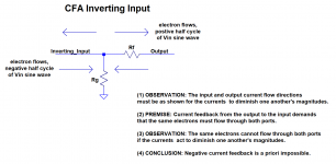
And where is your reply to the implication of your premise relating output and input stage current that negative current feedback is a priori impossible?
According to Wikipedia, Douglas Self and many others, a more precise definition of transconductance is dIout / dVinAccording to Wikipedia:
Transconductance (for transfer conductance), also infrequently called mutual conductance, is the electrical characteristic relating the current through the output of a device to the voltage across the input of a device
It's a VFA with a long tail pair as it used to be said : the sum of the emitter currents is constant, thanks to the constant current source loading the emitters.So, you can consider that, in a LTP, the voltage of the +input drive the *current* in its emitter resistance, and that the voltage on the - input feedback transistor affect the same *current* in inverse.
By the way, we could study the differential Rush pair, where the emitters are in series.
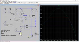
I understand what a buffered voltage source can be, I do not know what a buffered current is. A small simulation (attached figure) shows that the input transistor which receives the feedback voltage, does almost not change its Ie and Vbe with or without a buffer.Are-you concluding a VFA is a current feedback amplifier with a buffered current feedback signal ?

A loop game.Please, can't you stop this crazy game, turning round and round ?
Last edited:
It is to determine the electronic meaning of current feedback.Really? Where is this purpose stated?
Syn08 wrote before me what I was going to express, but much better than I can do.So Syn08's every comment is yours, then?
100 Hz.Yes. Are you using this as a reason not to reply to the question? Don't. Would you reply if I repeated the analysis at 20MHz? 3MHz? 50MHz? What frequency would engender a reply?
As, for me, negative feedback is always related to a voltage error (which generates an error current, not a feedback current), there is no impossibility related to a negative curent feedback which does not exist or at least, not correctly défined.And where is your reply to the implication of your premise relating output and input stage current that negative current feedback is a priori impossible?
I can't really follow how you drew this conclusion, but it is certainly wrong for a small signal analysis. If you think of a large signal analysis, then the transconductance is modified by many factors, at any moment in time, so I don't know how you would isolate a particular contribution. Sorry, I'm not a LTSpice camper, so I can't help interpreting the results straight from the simulator output.
Please re-read what I have written. I have never, ever claimed that gm changes with loop gain. Ever! You have obviously confused me with someone who has.
I have demonstrated with LTSpice, and have derived using the small signal AC low frequency Hybrid Pi model of a transistor, that the ratio ic/vbe of AC signals for a CFA inverting input transistor is unequal to gm (which is constant regardless of loop gain!) when the CFA operates in a closed loop.
This occurs because vbe is reduced by loop gain and therefore so is gm vbe, but vce is not, and so vce / ro is unaffected by loop gain. The currents produced by the two effects subtract at the collector and emitter terminals. Accordingly, as loop gain increases, gm vbe approaches vce /ro and we are left with the inequality.
If you can't simulate with Spice and you can't analyze a CFA using Hybrid Pi transistor models for input transistors, there is no way you can see this effect, and there is nothing for us to discuss. If you think it would help you see what I am talking about, I can forward the algebraic analysis.
According to Wikipedia, Douglas Self and many others, a more precise definition of transconductance is dIout / dVin
Oh, Crikey, fer cry-yi, yes, introduce calculcus, why don't ya! Just another attempt to misdirect and draw attention away from matters of substance. If we're going to go there, once again your statement is incomplete and therefore wrong. More precisely, transconductance is the partial derivative of collector current with respect to vbe, with vce held constant.
It's a VFA with a long tail pair as it used to be said : the sum of the emitter currents is constant, thanks to the constant current source loading the emitters.
By the way, we could study the differential Rush pair, where the emitters are in series.
I understand what a buffered voltage source can be, I do not know what a buffered current is.
Not that it has any relevance at all to what we are discussing, but a good example of a current buffer is to add a resistor to in the input of a three terminal positive voltage regulator. Connect the resistor leads to the base and emitter of a pnp BJT, and the collector to the regulator output. Voila, a current buffer at the regulator output.
A small simulation (attached figure) shows that the input transistor which receives the feedback voltage, does almost not change its Ie and Vbe with or without a buffer.
An externally hosted image should be here but it was not working when we last tested it.
A loop game.
I have no desire to go off on yet another tangent when you continue to refuse to answer prior questions.
Current feedback don't explain why CFA is driven by Vbe on low open loop gain and by Vce on high open loop gain.
It's not.
Please address the assertion in the attachment.I don't understand.
I just wrote I = V/R. you connect a resistor on a voltage source, and you have current.
Yup. And derived from conservation of current at a node, a current flows through a resistor and you have a voltage. You make no distinction between a voltage controlled current source and a current that flows through a resistor because of conservation of current.
Yes, I demonstrate it is a voltage feedback.
Not that I can see.
May be still my poor english, but you say that emitter current flows through collector, no ?
No. I say that all collector current flows through the emitter.
Two identical types of input stage ?
I don't understand.
No! Two identical types of input stage feedback.
Attachments
there is nothing for us to discuss.
Yes, I'm afraid so.
Have I anywhere attempted to put in your mouth "gm changes with loop gain"? If so, I apologize.
OTOH, I really don't understand why you would think the ic/vbe (as a ratio of small AC signal amplitudes) relationship with the (bias point defined, for a small signal analysis, always constant) gm=Ic/Vt is relevant in this discussion. In fact, I also fail to understand why ic/vbe is a relevant metric for any purposes, (dimensionally is the same as a transconductance, but that's where any resemblance stops).
But it's likely my total inability to follow your rationale and get your points.
Good luck debating and Happy Holidays!
It is to determine the electronic meaning of current feedback.
A reasonable assertion. How then to do it without ever more careful analysis?
Syn08 wrote before me what I was going to express, but much better than I can do.
Actually, forr, you have never made the mistake that Syn08 made, of thinking that I have claimed that gm changes with loop gain. Considering Syn08's comments, you'd be far better off speaking for yourself.
Please suggest VFA and CFA ICs with 100Hz unity gain bandwidths. Barring that, something that has a simulation file I can actually use.100 Hz.
As, for me, negative feedback is always related to a voltage error (which generates an error current, not a feedback current), there is no impossibility related to a negative curent feedback which does not exist or at least, not correctly défined.
Will you please respond to the reasoning that your claim leads to? You have said that because no output stage current flows into the input stage, there is no current feedback in a CFA.
But for negative current feedback to exist, input and output stage currents must mutually diminish. If they do, their directions must be such that the current from one stage cannot enter the other. Therefore, negative current feedback is impossible.
Ignoring this logic is not refuting it.
So if you say NOW that negative current feedback is not impossible, you should have no problem giving us an example in which no output stage current flows into the input stage, right?
Who is this guy ?Douglas Self
This author of these popularization books on audio filled with bias and certainties ?
While he was told here, by a member of this forum, that he cannot forget CFAs in a chapter dedicated to amplifiers topologies, his answer was: "Yes I can".
That said, his study on the "blameless" is not without interest for those who believe "Simple is beautiful".
If he is your guru or your reference, I better understand your strange way of seeing things, voltages and currents, chicken and egg.
I can not advise you too much to read the works of Bob Cordell (and Monsieur de La Palisse), instead.
I have not respected my own words, sayin "it will be my last words on the subject", please apologize, I could not resist because your attempt to put stupid
thoughts in my mouth " Audio amplifiers having 400 MHz bandwidth, our friend Tournesol will be the happiest man of the audio community." .
The fact is I'm not only in concern with distortion of standing waves, that can be easily measured and addressed to be, nowadays, lot under audibility, but the way an amplifier behave with musical fast transients.
Instead of loosing time and bandwidth with this controversy, why don't you play with a simple CFA schematic in LTspice, play with it to can feel the differences, build the best one you can design (or buy one) and...listen !
I am sure that all the people that had been interested in CFAs designs still use and had designed a lot of various VFAs in their life.
Can-i be flamed if I pretend CFA has a little different character in the way they reproduce music, and, if some has a preference for one or an other aspect of their "character", it is, indeed, a question of real preference, and not under some kind of marketing b.s influence.
On my side, I tend to prefer class D for sub bass, VFA for bass reproduction and CFA for treble. On a pure subjective way that cannot be disputed.
The best of the 3 worlds for me and everybody is free to have different preferences.
Happy Christmas to all of you, here, and your families.
Last edited:
Then again, a 'fast musical transient' in a 20kHz bandwidth can never be faster than a full amplitude 20kHz sine around zero crossing. So why singling that out specifically?
You see, the longer you make your posts, the greater the danger that nonsense creeps in ;-)
Jan
You see, the longer you make your posts, the greater the danger that nonsense creeps in ;-)
Jan
The Amplifier Institute.Who is this guy ? This author of these popularization books on audio filled with bias and certainties ?
I have all his books bar "Electronics for vynil". Even if you dislike Self's circuits, Douglas gives a huge amount of informations for serious designers.
I had his book from day one and know his Error Correction Amplifier since 1984, it was published in a Siliconix booklet. Bob Cordell has not yet published anything about CFA's. The 2nd edition of its book may approach the topic.I can not advise you too much to read the works of Bob Cordell (and Monsieur de La Palisse), instead.
I thought you did not lack sense of humor as being an Hergé's fan like me.I have not respected my own words, sayin "it will be my last words on the subject", please apologize, I could not resist because your attempt to put stupid words in my mouth " Audio amplifiers having 400 MHz bandwidth, our friend Tournesol will be the happiest man of the audio community." .
Musical transients are much slower than lab signals injected at amp inputs.The fact is I'm not only in concern with distortion of standing waves, that can be easily measured and addressed to be, nowadays, lot under audibility, but the way an amplifier behave with musical fast transients.
Subjective considerations are out of topic in this thread.Instead of loosing time and bandwidth with this controversy, why don't you play with a simple CFA schematic in LTspice, play with it to can feel the differences, build the best one you can design (or buy one) and...listen !
I am sure that all the people that had been interested in CFAs designs still use and had designed a lot of various VFAs in their life. Can-i be flamed if I pretend CFA has a little different character in the way they reproduce music, and, if some has a preference for one or an other aspect of their "character", it is, indeed, a question of real preference, and not under some kind of marketing b.s influence.
On my side, I tend to prefer class D for sub bass, VFA for bass reproduction and CFA for treble. On a pure subjective way that cannot be disputed.
The best of the 3 worlds for me and everybody is free to have different preferences.
Last edited:
So sure of you and contemptuous to others ?Then again, a 'fast musical transient' in a 20kHz bandwidth can never be faster than a full amplitude 20kHz sine around zero crossing. So why singling that out specifically?
You see, the longer you make your posts, the greater the danger that nonsense creeps in ;-)
Consider a speaker and the difference of power you apply to it between a square wave and a rounded one or a one with overshoot.
Too, are-you so sure that 20Khz (or less) of limit of our listening capabilities of standing waves means that the same limitation exists with transients ?
Just try to play with a 40Kz 1/3 oct corrector on a female voice, by example. Using a digital device to eliminate the phase effects.
Sorry, but i listen with my ears and my brain, not with any theoretical hypothesis. then i try to understand.
Do not take my awkwardness in English with a lack of thought or personal experiences.
To Forr, sorry, but it is impossible, on my opinion, to separate audio discussions from "Subjective considerations". Unless you consider amplifiers as measuring instruments.
I don't dislike Self's circuits, i dislike its attitude.[Even if you dislike Self's circuits, Douglas gives a huge amount of informations for serious designers.
According to him, a chapter about CFA has been added.Bob Cordell has not yet published anything about CFA's. The 2nd edition of its book may approach the topic..
Last edited:
Consider a speaker and the difference of power you apply to it between a square wave and a rounded one or a one with overshoot.
Your description of that signal is rather ambiguous so can be anything. The important question is: does it have components above 20kHz? If not, it will be faithfully reproduced by an amp (I noted that you silently moved from amp to speaker but I will pull it back if that's OK with you) it will faithfully be reproduced by an amp with low distortion in the audio band, let's say for the discussion less than 0.01% at all levels and frequencies.
If your hypothetical signal has components outside the audioband, you are measuring the amp with signals it is not supposed to be fed with.
Jan
PS I do know that things are not black and white and that it is not so that it will be good at 20,000 Hz and bad at 20,001 Hz. But for discussion purposes it is generally better to be quite clear.
I don't dislike Self's circuits, i dislike its attitude.
So it's not that you don't like the contents, but you dislike the way it is presented?
I know that Mr. Self is outspoken on matters, but as a reader you should be able to 'look through' that and be able to judge the contents on its merits.
Or if you are unable to do that, don't read the book ;-)
Jan
Yes, I'm afraid so.
Have I anywhere attempted to put in your mouth "gm changes with loop gain"? If so, I apologize.
OTOH, I really don't understand why you would think the ic/vbe (as a ratio of small AC signal amplitudes) relationship with the (bias point defined, for a small signal analysis, always constant) gm=Ic/Vt is relevant in this discussion. In fact, I also fail to understand why ic/vbe is a relevant metric for any purposes, (dimensionally is the same as a transconductance, but that's where any resemblance stops).
But it's likely my total inability to follow your rationale and get your points.
Good luck debating and Happy Holidays!
This forum is not perfect. Others have noted the difficulty in communicating and sometimes getting even simple, demonstrable points across.
I still have no idea why you think I claimed that gm varied. Since the only thing that I did vary was loop gain, I assumed that that was part of the explanation. Sorry if I misconstrued.
I am also mystified that you see no relationship between gm and ic/vbe.
But I do think there is some combination of too much miscommunication and misunderstanding to pursue our discussion further.
Good luck debating and Happy Holidays!
The best advice I have heard for power amps is an output slew rate of 1V/us per peak output voltage. You can then relate the required bandwidth from BW = SR/2*Pi*Vopeak (rearrange the formula accordingly).
I am afraid blindingly fast power amps (BW and SR) still have to deal with reactive loads so there is a limit to how much speed is any good. It’s a bit like the distortion wars where people proudly talk about 1 ppm distortion (yes, I am guilty too). What is the point other than the intellectual challenge? Your speakers are many orders of magnitude higher. Worse than all that, there is no correlation between high speed, low distortion, and musical appreciation.
I am afraid blindingly fast power amps (BW and SR) still have to deal with reactive loads so there is a limit to how much speed is any good. It’s a bit like the distortion wars where people proudly talk about 1 ppm distortion (yes, I am guilty too). What is the point other than the intellectual challenge? Your speakers are many orders of magnitude higher. Worse than all that, there is no correlation between high speed, low distortion, and musical appreciation.
Happy Holidays!
Happy holidays Ovidiu, Scott and the rest of the gang.
BTW O: It's impossible to discuss with people like CPaul.

- Home
- Amplifiers
- Solid State
- Current Feedback Amplifiers, not only a semantic problem?