So in fact you have separated the voltage amp from the current amp, just like I did, true ?
Hans
Yes, the 'Vas' is another HEC-corrected circuit with another AD844. The name pf the paX amp stands for power amplifier eXperimental.
Jan
Attachments
You think so ? Here is a document by a guy who perfectly understood your Pax circuit. He loved it, I think he is very glad to see you refering to it today but probably smiles when reading your today comment. He explained the circuit to his audio sisters and brothers and you cordially congratulated him at the time.Yes. The circuit around the AD844 is in concept (and execution) very simple, straightforward, but almost nobody sees it because it is so unusual. When explained, they all say - but of course! 😎
And of course if your mindset is in denial of current feedback, no way you are going to understand it! Jan
http://iodau.pagesperso-orange.fr/
The linked document has not been modified since ten yeas ago. Guess who is the author. A clue : he is contesting the validity of the CF concept with such argument as : the input stage of the AD844, claimed to be a CFA, is an almost ideal transistor (*) keeping the fundamental feature of a transistor, which is to be a differential voltage controlled device.
(*) https://www.edn.com/electronics-blo...ansistor-?utm_source=Aspencore&utm_medium=EDN
Last edited:
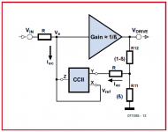
O.k. got it. The left {RR} resistor has taken over the role of the separate Rg.Hans, what I posted was a simpler circuit (one less resistor). I also varied the resistor values over a wider range to test the limits of the idea. It was easy to look at both output voltage and input current, so I did. The results still allow you to distinguish between VFAs and CFAs.
But there's no need to also let the right {RR} resistor take all the steps.
This one could have been left at a fixed value.
But its a nice discriminator, isn't it ?
Hans.
I like the clever simplicity of your design.Yes, the 'Vas' is another HEC-corrected circuit with another AD844. The name pf the paX amp stands for power amplifier eXperimental.
Jan
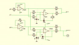
This is how I realised the error correction in my current amp, a dual nested AEF, quite a bit more complicated as yours.
The only advantage over HEC is that there are no critical resistor values.
Hans
Attachments
Hah! If you want weird uses for the AD844, try to parse this! 😀
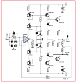
Output stage of my paX amp.
Jan
OK... we are now into sharing over the holidays are we... nice...
Attached is the output stage of an amplifier I designed I believe about 30 years ago... as no doubt that someone thought of before me. My brother in law is still using it to this day.
Instead of current mirrors off the power supply rails the current mirrors are located to track Vout. The network separates the input VFA amplifier, as constructed of small high speed transistors from the CFA output buffer as larger slower devices. The RL parallel network consisted of around 100 Ohms as I remember... and paralleled by an open core coil of perhaps 10 turns.
The RL network was there to disconnect delays and capacitances of the output from interfering with the high speed input VFA network. The inductor was there to short circuit the output to the current mirror emitters at low audio frequencies, as to thereupon maximize corrective feedback current.
Attachments
O.k. got it. The left {RR} resistor has taken over the role of the separate Rg.
But there's no need to also let the right {RR} resistor take all the steps.
This one could have been left at a fixed value.
But its a nice discriminator, isn't it ?
Hans.
Yes, you're right - no need to vary the right resistor. And yes, it is a nice discriminator. I can't think (not yet at least 🙂 ) of any way to poke a hole in it.
When we prevent negative feedback from obscuring how circuits actually work, we can see some things more clearly.
But I suspect we can simply add this to the list of things that forr will ignore:
(1) the necessity of Rg and in(-) currents to diminish each other for negative current feedback to occur, which of course means that Rg current cannot flow into in(-). Since he concludes that such a situation rules out current feedback, the inexorable corollary is that negative current feedback is a priori impossible;
(2) the role of the Early Effect in a CFA inverting input transistor in preventing almost all of the Ebers-Moll transconductive current from escaping from the collector (and emitter) in high gain closed loop operation, thereby calling into question the whole "CFA employs v.f." paradigm, and;
(3) your topological discriminator showing that a CFA does not work like a VFA.
Last edited:
You can't consider the role of the Vbe as secondary. Think of how the input signal is inserted in the circuit.lifier, the output signal is fed back to the emitter of the input transistor, be it a single ended or diamond buffer, via low value resistors, rf & rg. So here we have a large current flowing from (to) output, through feedback resistors, through the emitter/collector of the input transistor, feeding the vas/tis with whatever current required. Of course there is the vbe of the input transistor in play as well, but in this case the current through the complete feedback loop is by far the dominant factor. So with all this current flowing through the feedback loop, why not just call this a current feedback amplifier?
Intermezzo
http://web.mit.edu/6.933/www/black.pdf
I was curious about the number ot times author Mindell was quoted at DiyAudio. Only twice, by you.
This morning I came upon this paperHarold Black had just developed his feedback amplifier concept a couple of years earlier, and Hendrik Bode was an upcoming hotshot at Bell Labs iirc.These guys did experiment a lot with what we would call voltage feedback and current feedback, in the vintage sense - the name related clearly to the controlled quantity, NOT whether the feedback signal was in the form of a voltage or current.
BTW A large part of the discussion was whether to keep a man in the loop (which, obviously, the US Navy wanted) or to make it fully automatic, what the Bell Labs guys wanted. The compromise they reached in itself is interesting to read.
Bush'es book is more from the political and managerial viewpoint; for the tech details read David Mindell's 'Between human and machine - Feedback, Control, and Computing before Cybernetics'.
Especially Chapter 9, 'Analog's Finest Hour'.
As Bode himself commented in 1940:
"The engineer who embarks on the design of a feedback amplifier must be a creation of mixed emotions. One the one hand, he can rejoice in the improvements in the characteristics of the structure which feedback promises to secure him. On the other hand, he knows that unless he can finally adjust the phase and attenuation characteristics around the feedback loop so the amplifier will not spontaneously burst into uncontrollable signing, none of these advantages can be actually realized."
Don't you wish you lived in that time? A time were stuff was not just rehashed innumerable times, but when you could actually find out something that no one had found out before you! ;-)
http://web.mit.edu/6.933/www/black.pdf
I was curious about the number ot times author Mindell was quoted at DiyAudio. Only twice, by you.
Can you give a very simple and basic example where Rg current flows into in(-) and describe the effect ?(1) the necessity of Rg and in(-) currents to diminish each other for negative current feedback to occur, which of course means that Rg current cannot flow into in(-).
I like the clever simplicity of your design.
This is how I realised the error correction in my current amp, a dual nested AEF, quite a bit more complicated as yours.
The only advantage over HEC is that there are no critical resistor values.
Hans
Hans is this inspired by Giovanni Stochino's articles in Linear Audio?
I admit I am struggling to grok it, but in my experience the overriding difference between good old negative feedback and any form of error correction or feedforward is that the latter two always need some matching of resistors in some shape of form. And that the limit to the matching in the final analysis forms the limit of the non-linearity reduction achievable.
Jan
As many others, Bonsai tried an other "error cancellation", using a comparator to extract the "error" signal between input and output of the power amp, adding some of it in the feedback.
A way to increase the feedback ratio without touching to the OL amplifier gain.
I tried too this idea some decades ago, but abandoned-it after listening: I had found that the audible improvement (if any) is not worth the complexity, the fights with phase turns at hf, precise adjustment of the common signal rejection and the quest for a fast and low distortion OPA.
The discussion is lost somewhere in one of the 3 volumes of the "John Curl's Blowtorch preamplifier" encyclopedia.
I don't know if Bonsai had realized-it IRL in one of his productions ?
Last edited:
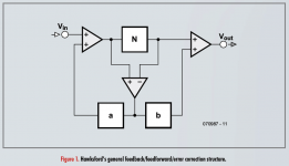
Your 'comparator' is how Hawksford type EC works. Hawksford generalized it as in the attached, showing that you could use error feedforward (b) or error feedback (a), or a combination, as long as the sum is exactly 1 for max suppression of errors.
Stochino has made a lot of efforts to the feedforward method with very good performance, as described in his Linear Audio articles.
I liked more the feedback error system. But please realize that it is all still nfb in disguise; the pos feedback part increased the ol gain to theoretically infinity which means that the nfb part has a lot of gain to work with to reduce error. But, as always, Mother Nature puts a stop to it for stability reasons 😎
Jan
Attachments
Jan,Hans is this inspired by Giovanni Stochino's articles in Linear Audio?
I admit I am struggling to grok it, but in my experience the overriding difference between good old negative feedback and any form of error correction or feedforward is that the latter two always need some matching of resistors in some shape of form. And that the limit to the matching in the final analysis forms the limit of the non-linearity reduction achievable.
Jan
The subject of AEF kept me busy before these articles, that's why I reacted on Giovanni's articles with several comments.
But it was great to read the articles in your Linear Audio and see the subject from different viewpoints in different forms.
Hans
Can you give a very simple and basic example where Rg current flows into in(-) and describe the effect ?
The attached is all set up to run. RLOAD was added so that loop gain could be artificially reduced and the resultant changes in the Early (R2), transconductance (G1), and collector/emitter ( I(V4) ) currents could be monitored.
Increases in loop gain have no effect on vce and therefore the Early effect, which makes an unchanging current contribution.
The Early and transconductive currents are subtractive, and so as the originally small loop gains increase, vbe and therefore the transconductive current falls until it reaches a point slightly larger than the Early current. It continues to approach the Early current asymptotically, but never falls below it no matter how large the loop gain becomes. This is so that there is always enough collector current ( the difference between the two) to keep the circuit operating.
Attachments

As many others, Bonsai tried an other "error cancellation", using a comparator to extract the "error" signal between input and output of the power amp, adding some of it in the feedback.
A way to increase the feedback ratio without touching to the OL amplifier gain.
I tried too this idea some decades ago, but abandoned-it after listening: I had found that the audible improvement (if any) is not worth the complexity, the fights with phase turns at hf, precise adjustment of the common signal rejection and the quest for a fast and low distortion OPA.
The discussion is lost somewhere in one of the 3 volumes of the "John Curl's Blowtorch preamplifier" encyclopedia.
I don't know if Bonsai had realized-it IRL in one of his productions ?
I think you re talking about what I have called 'AFEC'. Hitachi tried this idea in the early 1980's (someone brought this to my notice after I put the AFEC idea up on diyaudio), but good wide bandwidth low distortion opamps for the error correction amplifier were not available and it seems they abandoned the idea - an NE5534 is not quite good enough for the job. No doubt the fact that the feedback bridge required accurate balancing was also a factor in their decision.
However, today we have very good dual opamps like the LM4562 (there are many others just as good) with ppb distortion, good output drive capability, and very wide bandwidth that are perfect for AFEC. The error correction augmentation amplifier only operates in the small signal regime - which is the same for nested feedback systems as well BTW. The slew rate of the power amplifier therefore remains unaffected (250 V/us in a practical amplifier example).
AFEC is a bit more complex than a straight nested feedback amplifier because you have to null the feedback bridge distortion but I can attest to the fact that it works exceeding well and the distortion reduction is wide band.
If you start with a good power amp - so distortion at full power <30ppm, AFEC will get you to ~1ppm (1kHz) with just a little bit of feedback loop 'nudging'.
Augmented Feedback Error Correction (AFEC)
Last edited:
This all brings memories back - I sort of independently discovered this stuff in 1996 and succeeded to present it at the AES convention in NY in 1997.
At the end of my talk a guy got up and stated that he thought it was all BS (although he was polite about it, being British). Later I went to talk to him and he turned out to be no one else than Malcolm Omar Hawksford...
Jan
At the end of my talk a guy got up and stated that he thought it was all BS (although he was polite about it, being British). Later I went to talk to him and he turned out to be no one else than Malcolm Omar Hawksford...
Jan
Attachments
One more, then I will shut up: I got even with him years later when I went to Essex to interview him for AudioXpress under the name The Essex Echo, which was also the name under which MOH wrote columns earlier for Audio magazine iirc.
https://linearaudio.nl/sites/linearaudio.net/files/Didden-Hawksford_Part1.pdf
https://linearaudio.nl/sites/linearaudio.net/files/Didden-Hawksford_Part2.pdf
Jan
https://linearaudio.nl/sites/linearaudio.net/files/Didden-Hawksford_Part1.pdf
https://linearaudio.nl/sites/linearaudio.net/files/Didden-Hawksford_Part2.pdf
Jan
This all brings memories back - I sort of independently discovered this stuff in 1996 and succeeded to present it at the AES convention in NY in 997.
At the end of my talk a guy got up and stated that he thought it was all BS (although he was polite about it, being British). Later I went to talk to him and he turned out to be no one else than Malcolm Omar Hawksford...
Jan
Yes - similar scheme in many ways - did you build it?
Is MH still around? Must be quite an old guy now. I recall he wrote a paper about cable directionality - I'd say that was the real BS.
Last edited:
Hi Bonsai,The error correction augmentation amplifier only operates in the small signal regime - which is the same for nested feedback systems as well BTW. The slew rate of the power amplifier therefore remains unaffected (250 V/us in a practical amplifier example).
Could you be so kind to explain what you mean with small signal regime and why therefore slew rate should remain unaffected.
And is it good or bad that the slew rate remains unaffected.
Hans
Nice to read those things from the past.This all brings memories back - I sort of independently discovered this stuff in 1996 and succeeded to present it at the AES convention in NY in 1997.
At the end of my talk a guy got up and stated that he thought it was all BS (although he was polite about it, being British). Later I went to talk to him and he turned out to be no one else than Malcolm Omar Hawksford...
Jan
Now it begins to become clearer how you got to know so many people.
Hans
- Home
- Amplifiers
- Solid State
- Current Feedback Amplifiers, not only a semantic problem?