vzaichenko,
What is there and what is not there, what is truth and what is not truth is a matter of judgment. As Jesus said, do not deceive yourselves, use sound judgment. Sadly, he would not say what truth is.
keantoken,
In that abstract concept representation, the category is the thing.
Hierfi,
You are right, "to think" would have been less confusing than "to consider as".
I do like your approach, but cannot accept it factually. Did you come up with it hastily to prove the existence of feedback? It contains a number of inconsistencies and disturbing formulations.
Causality (a part of determinism) is a paradoxical axiom, particularly when applied to physics.
"Dielectric field" is somewhat unorthodox in this context.
Logically, an entity is either constant or variant. On the other hand, a theory can indubitably be both absolute and relative at the same time. Maybe that`s why it is so special and popular.
He could be right. I was just amazed with the stability of the design. I have been wondering if JLH had SPICE back then (?)
JLH had Spice in his head. It's called circuit analysis.
The notion that you can't design a good circuit unless you have Spice is, well, incredible.
Jan
JLH has designed many amps. Soundwise this one to me is subjectively less favorable then some of his other designs. But looking through Spice, I admired this amp the most. It is special in many area including stability. Calling it "by accident" is also an admiration.
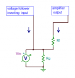
The arrows represent currents. Would you design the arrow coming from the amplifier output through Rf in the inverse direction ?Currents, like voltages, can be positive or negative. Arrow directions mean little on a schematic unless the associated meanings are further defined, for instance by naming the arrows and relating the names with equations.
I think I can maintain that.I think I recall you arguing that since the current through Rf does not flow through the CFA's in (-), this can't be current feedback.
Correct or not, the rest of this post is worth to comment.If this is incorrect, please say so and disregard the rest of this post.
It think you forget :Consider the case in which in (-) is being fed by the Thevenin equivalent of the standard Vout, Rg, Rf circuit: a voltage source equal to Vout * Rg / (Rg + Rf) in series with a resistor Rfg = Rg || Rf. (The open loop output impedance is neglected here for simplicity, but could be accounted for.)Surely the same current from the Thevenin voltage source flows through both Rfg and in (-). Can we agree that this can be called current feedback? If not, please say so and disregard the following.in (-) cannot distinguish between these two circuits. The difference between them is the difference between the outputs and the feedback networks. Am I correct in assuming that this difference is enough for you to declare that the CFA does not employ current feedback?
- that in- is a voltage source which defines the feedback current (as this one is usually called).
- that the current from in- and from the output are in phase.
- that they add in Rg whose voltage across control by the voltage at in-.
If, for a given input voltage, current in Rf increases, current from in- decreases and vice versa.
That's the meaning of the arrows. The graph with the arrows should greatly help those who worry about the load by the impedance of in- as seen by the junction between Rf and Rg.
Attachments
Last edited:
🙂JLH had Spice in his head. It's called circuit analysis.
The notion that you can't design a good circuit unless you have Spice is, well, incredible.
>90% of the topologies we use today in analog audio were invented long before computers exist.
As the ground was almost virgin, the creative process to have original ideas was a requisite (and fun), including a special 'feeling'. As working with real devices on the bench was a longer process, as measurements were long and boring, if you use-it at each step, this involved the development of a greater capacity for auditory analysis.
It's amusing to see that today, where computers are entrusted to work, the simple reference to "listening" looks (sounds) incongruous and makes you ironic remarks about golden ears ;-)
I also note that, thanks to advances in computer simulations, technology is making incredible progress, and remarkable "performance" is being achieved. At the same time, the objects that surround us become "boring" and devoid of "personality". Cars are a good example.
Yeah... you turned a VFA into a CFA.
I wouldn't put it that way. In my mind, the terms CFA and VFA should apply to circuit topologies. This is a separate question from which type of feedback predominates in a given circuit.
DIT analysis shows that for certain combinations of feedback network component values, voltage feedback can predominate in a CFA. I'm pretty sure that DIT would show that current feedback predominates in the VFA circuit I posted.
The arrows represent currents. Would you design the arrow coming from the amplifier output through Rf in the inverse direction ?
First of all, thank you for your reply.
I’m sorry, but in the convention I and others have used extensively, the displayed arrows are ambiguous. Suppose i1 = i2 + i3. This would mean one thing if I named the arrows i1 and i2, and another if I named them i1 and -i2.
I think I recall you arguing that since the current through Rf does not flow through the CFA's in (-), this can't be current feedback.
I think I can maintain that.
For negative feedback to occur in a non-unity closed loop gain CFA, the relative directions of the Rf and in(-) currents must be (and are) such that the former acts to diminish the latter. This also means that the Rf current cannot enter in (-). Your assertion leads inexorably to the conclusion that negative current feedback is a priori impossible in any circuit. Obviously, I reject this conclusion as unreasonable, which forces me to reject your assertion which demands it.
It think you forget :
- that in- is a voltage source which defines the feedback current (as this one is usually called).
I didn’t forget it, but I do reject it, at least as a complete description of how the transistor is working. In my “complex circumlocution” (which it is now clear that no one rejects) I show that in a high loop gain CFA, the current due to the Early Effect is as significant as that from the transconductive effect that you rely upon to claim voltage feedback. The Hybrid Pi model shows the ro “Early” resistor between the collector and emitter. The current flowing through ro terminates in the low impedance current mirror, clearly an incidence of current feedback. As I have been saying for hundreds of posts, you need to face this fact and address it.
I wouldn't put it that way. In my mind, the terms CFA and VFA should apply to circuit topologies. This is a separate question from which type of feedback predominates in a given circuit.
DIT analysis shows that for certain combinations of feedback network component values, voltage feedback can predominate in a CFA. I'm pretty sure that DIT would show that current feedback predominates in the VFA circuit I posted.
Chris,
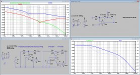
I've put your LT1001A circuit through the DIT test and also through the test that I designed.
The DIT at the left is a bit going up and down, but for the most part the circuit is identified as a VFA.
My own test at the right is even much more conclusive in identifying the circuit as a VFA.
Hans
Attachments

I wouldn't put it that way. In my mind, the terms CFA and VFA should apply to circuit topologies. This is a separate question from which type of feedback predominates in a given circuit.
Granted. For reasons that external networks are applied afterward it follows that CFA and VFA attributes to them are correct in consideration that they will be used most commonly with equivalent resistances (paralleling of Rg and Rf) as falling between the lower source resistances of CFA's and higher source resistances of VFA's.
DIT analysis shows that for certain combinations of feedback network component values, voltage feedback can predominate in a CFA. I'm pretty sure that DIT would show that current feedback predominates in the VFA circuit I posted.
I am not following DIT analysis and am suggesting that it would be incorrect if it came up with the outcome as a VFA. My argument here is that for the same reasoning as above the VFA has some value of inverting terminal output resistance, perhaps 20K Ohm, that by inclusion of the current source being fed back to it as being in series with resistors connected at the output causes feedback resistance to far exceed the 20K Ohm... as ideally infinite.
Effectively I am saying that there exists a dominance battle between Vout of the device and Vout of the input buffer at the inverting terminal, it being the reference point where dominance is determined. The battle is over the equivalent resistances of the output network attached to the inverting terminal and its own internal output impedance.
Chris,
I've put your LT1001A circuit through the DIT test and also through the test that I designed.
The DIT at the left is a bit going up and down, but for the most part the circuit is identified as a VFA.
My own test at the right is even much more conclusive in identifying the circuit as a VFA.
Hans
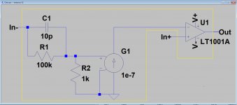
Hans, you're not testing the circuit I posted with the current source driving the in (-) input.
In the circuit you tested, the impedance looking into the fb network is much lower than that looking into in (-). It is no surprise you conclude that vf predominates.
And again, I would argue that to be precise, you are testing what form of feedback predominates, not the name of the type of op amp.
🙂
As the ground was almost virgin, the creative process to have original ideas was a requisite (and fun), including a special 'feeling'. As working with real devices on the bench was a longer process, as measurements were long and boring, if you use-it at each step, this involved the development of a greater capacity for auditory analysis.
🙂 😎
I started using CAD/SIM from its inception. But I still rely on T&M before I would fully trust a SIM.. any sim normal people can afford or the free ones. [Though I can say I have one patent and money making product which was done 100% in CAD/SIM first.] And, you cannot listen to your design progress and learn the sound of such changes with CAD.
I am not a circuit designer much. I only designed a few audio circuits in my life as a hobby and none of them used CAD/SIM. I would not have even done those few if I didnt love music and think i could do better than what was being offered for sale. Though the debate about how a CMA and VMA works internally is bordering on interesting at times, the listening part is still important.
THx-RNMarsh
Last edited:
OK.Granted.
I am not following DIT analysis and am suggesting that it would be incorrect if it came up with the outcome as a VFA. My argument here is that for the same reasoning as above the VFA has some value of inverting terminal output resistance, perhaps 20K Ohm, that by inclusion of the current source being fed back to it as being in series with resistors connected at the output causes feedback resistance to far exceed the 20K Ohm... as ideally infinite.
Effectively I am saying that there exists a dominance battle between Vout of the device and Vout of the input buffer at the inverting terminal, it being the reference point where dominance is determined. The battle is over the equivalent resistances of the output network attached to the inverting terminal and its own internal output impedance.
I'm afraid I don't entirely understand what you are saying. I do believe that a comparison of the impedances looking in both directions at in (-) will establish what DIT will: the predominant form of feedback in the circuit.
Could you please explain further the point you are making above?
Hi Chris,Hans, you're not testing the circuit I posted with the current source driving the in (-) input.
In the circuit you tested, the impedance looking into the fb network is much lower than that looking into in (-). It is no surprise you conclude that vf predominates.
And again, I would argue that to be precise, you are testing what form of feedback predominates, not the name of the type of op amp.
Are we having a miscommunication again ?
My one and only intention was to testing the form of feedback that predominates and not the name of the type of op amp.
Please tell me what is wrong in the set up I used, because it's the exact circuit that you presented, see below.
Hans
Attachments

If the current in Rf increases, the current from in- decreases and vice versa, thanks to the voltage under the control by the emitter.For negative feedback to occur in a non-unity closed loop gain CFA, the relative directions of the Rf and in(-) currents must be (and are) such that the former acts to diminish the latter. This also means that the Rf current cannot enter in (-). Your assertion leads inexorably to the conclusion that negative current feedback is a priori impossible in any circuit. Obviously, I reject this conclusion as unreasonable, which forces me to reject your assertion which demands it.
I read quite a lot of texts on CFA, it seems to be that it is the in- emitter current which is called the current feedback. But that's adhering to the CF concept, which I do not. The current of major interest in input stages is the collector current.I didn’t forget it, but I do reject it, at least as a complete description of how the transistor is working. In my “complex circumlocution” (which it is now clear that no one rejects) I show that in a high loop gain CFA, the current due to the Early Effect is as significant as that from the transconductive effect that you rely upon to claim voltage feedback. The Hybrid Pi model shows the ro “Early” resistor between the collector and emitter. The current flowing through ro terminates in the low impedance current mirror, clearly an incidence of current feedback. As I have been saying for hundreds of posts, you need to face this fact and address it.
I suppose that in simulation the transistor models take care of ro. The Early effect can be circumvented by cascoding the in- transistors. I've never seen done with CFA inputs so it is difficult to see it as an issue.
Insert a capacitor in parallel with Rf of a CFA where Rg is 50 ohm and you will see that CFA don't turn into VFA behaviour.
Hmmm. Where have I also suggested that before?
Seemed to me, explaining that behavior tells a lot about how the circuit is operating.
🙂
-RNM
Last edited:
You're right.Insert a capacitor in parallel with Rf of a CFA where Rg is 50 ohm and you will see that CFA don't turn into VFA behaviour.
By inserting a cap par. to Rf, a CFA is not turned into a VFA but (very likely) into oscillator.
To confirm my suspicion I tried this with a LT1395 with Rg=50 Ohm and Rf=350 Ohm and by placing a cap parallel to Rf I ran into oscillations.
Because Rf is in par. with Z(s), the cap will try to extend the bandwidth of the CFA which is a no no.
Hans
Hi Chris,
Are we having a miscommunication again ?
Hans
Hans, perhaps. You put the op amp I used in a circuit of your design and tested that circuit properly.
You did not test the circuit I posted, for which I made the supposition that cf dominates.
No I did notHans, perhaps. You put the op amp I used in a circuit of your design and tested that circuit properly.
Sorry but you are wrong, I used the whole thing including everything.You did not test the circuit I posted, for which I made the supposition that cf dominates.
Please have another look at the circuit that I used below.
When I connected something wrong, tell me.
Hans
Attachments
Last edited:
If the current in Rf increases, the current from in- decreases and vice versa,
yes
thanks to the voltage under the control by the emitter.
This is an oversimplification.
I read quite a lot of texts on CFA, it seems to be that it is the in- emitter current which is called the current feedback. But that's adhering to the CF concept, which I do not. The current of major interest in input stages is the collector current.
... all of which flows through the emitter. And almost all of the very same current that flows through the emitter flows through the collector. The currents are practically identical.
I suppose that in simulation the transistor models take care of ro.
Yes, as Post 1028 confirms.
The Early effect can be circumvented by cascoding the in- transistors. I've never seen done with CFA inputs so it is difficult to see it as an issue.
It is not an issue and that is why there is no effort to cascode - the circuit works just fine in spite of it! But simply because it is not an issue does not mean that it is not a real phenomenon.
In the attached simulation, the transistors connected to the in (-) input have been replaced with their Hybrid Pi small signal low frequency AC models. (Hybrid Pi is derived from the Ebers-Moll/Early equation ic = Is exp (Vbe / VT) ( 1 + Vce/VA) .) Accordingly, the inputs are AC-connected. The DC bias for the following transistors is maintained by the added DC current source I2.
The resistor RLOAD has been added so that the loop gain can be varied. As you vary it, you can see what happens to the currents through R2 and R4 verses those through G1 and G2. At high gains (RLOAD removed or set to 1 Gig), their magnitudes are virtually equal and only their small difference flows through the collector and emitter. In this case, the transistor is certainly not an ideal transconductor.
Attachments
- Home
- Amplifiers
- Solid State
- Current Feedback Amplifiers, not only a semantic problem?