Is that a picture of Waly?
Bonsai, you're obviously not a First Generation Star Trek fan.
I would think that they are dependent.
This is something that I didn't realize at first. In any change of voltage the amplifier requires an impetus as the driving force for the output to potentially overshoot, as to be then reduced by feedback. In the instant voltage is applied, as prior to feedback correction, drive current is magnified by the equivalent parallel combination of Rg and Rf. This early onset current must be passed into the current mirrors as sourcing current into the Tz node resistance in the proper phase.
As others have suggested there must be a load on the inverting terminal for an initial impetus current to exist, as to then be diminished by feedback. Without it there is no output to be corrected by feedback.
So, please, accept my apologies.For the last time I'm not Waly.
I agree.Hence, the inverting terminal can only source signal currents, hence with an outward pointing arrow. This seems ought to be agreeable as the starting point of further analysis.
According to you, to stay in line with CFA theory, what is the frequency limit for what you name DC ?Originally Posted by forr
The low impedance of the (inverting) input (let's say 20 Ohm) has the strange property that it does not load Rg (let's 200 Ohm). This has been approached in the thread.
Quite correct and fully in line with CFA theory at DC
There are those here obviously determined to not listen to any reasoning along other than their predetermined path even to the point of silly comments.
Just to be forthright your logic is so limited as to bore me Scott. It is the fool that dismisses input solely on the basis of who submitted it.
So I would ask you this. What do you call a CFA that connects its output directly to the inverting input terminal?
What do you call a CFA that connects its output directly to the inverting input terminal?
An oscillator of course. Get your VFA to do that.
Let's suppose a closed loop CFA using a high value variable resistance firstly set at 100% as RfOriginally Posted by forr
It does not matter the sign convention is arbitrary, this is arguing trivia.
Let's inject an AC voltage (a few mV to avoid overloading the circuit), at the in+. Because of the voltage following property of the inverting input, the voltage across Rg is very close to the input voltage.
It would be very strange if someone did not the arrow pointed at Rg ?
Decreasing the setting of Rf will decrease the voltage across Rg. The AC current from inv- certainly decreases and the gain loop increases but is there any reason to change the direction of the arrow ?
An oscillator of course. Get your VFA to do that.
OK... seriously and with all due respect. I use CFA's all the time and spend a lot of time in compensating them. The AD844 provides access to the Tz node point thus allowing drastic gain reduction as well as frequency compensation to support that connection. Hence the question remains "What do you call a CFA that connects its output directly to the inverting terminal?"
OK... seriously and with all due respect. I use CFA's all the time and spend a lot of time in compensating them. The AD844 provides access to the Tz node point thus allowing drastic gain reduction as well as frequency compensation to support that connection. Hence the question remains "What do you call a CFA that connects its output directly to the inverting terminal?"
Connect the output of the AD844 directly (R = 0) to the -input then hang whatever you need on the Tz node to make it stop oscillating and still say it's a particularly useful circuit. I'll remind you there are very few CFA's with exposed Tz nodes. You are being simply argumentative for the point of being argumentative.
Hi Hervé,

By the way, one reason why I became an audio fan is this image, it fascinated me when I was a child.

No idea but I am pretty sure that Tryphon has a golden ear (the left one).Hi Forr,
Do you think Tryphon calculate the inverting input closed loop impedance before claiming it is low wrt Rg ?
Like for example comparing both and listening to see if there is audible differences ?
By the way, one reason why I became an audio fan is this image, it fascinated me when I was a child.
At least I calculated the R2/R1, where R2 is the feedback serial resistance, and R1 the common emitters resistance that is better to keep low, despite dissipation, to minimize the parasitic capacitances at the emitters and their negative effects at HF ;-)Hi Forr,
Do you think Tryphon calculate the inverting input closed loop impedance before claiming it is low wrt Rg ?
Happy you confirm that impedance of the emitter in a CFA can be negligible in front of their common source resistance if we set-it low enough:
In the brevity, CFA source resistances can be typically 50 Ohms, while VFA source resistances can be beyond 20K Ohm. It is considered that values in the parallel combination of Rf and Rg normally fall in between these two values, hence can differentiate a CFA from a VFA. This also leads to the conclusion that Thevenin equivalent resistances (the parallel combination of Rg and Rf) that fall below 50 Ohms turns a CFA into a VFA, and values exceeding 20K Ohm turns a VFA into a CFA.
That is the key on my point of view. And the fact that in a CFA, the feedback signal is subtracted in the same device to the original signal. (poles).
To resume my experiences, comparing the two topologies, everything equal (LowZ in both feedback paths)
VFA offers:
- Better ripple rejection in differential mode at low frequencies (<500KHz),
- A lot better ripple rejection in common mode at low frequencies (<500KHz)
- A little less noise ?
CFA:
- Better ripple rejection in differential mode at high frequencies (>500KHz),
- Litle better ripple rejection in common mode at high frequencies (<500KHz),
- A lot higher slew rate and little higher bandwidth. (current on demand).
About distortion, a very light advantage to CFA in harmonic distortion, they play equal in intermodulation.
This low z in feedback path is natural in CFAs, a problem in VFAs in audio, if you want to keep the symmetry and its influence on DC offset and distortion.
IF we set the input impedance at 10KO in a VFA, the open loop is reduced by ~4 oct comparing to CFA (by example 1MHz VS 4MHz.), noise increase at the advantage to CFA.
If we use the extra transistors in the VFA to build capacitance multiplier filters that will power the input and VAS stages, ripple rejection will be, now, better in the CFA ;-)
To conclude, as both topologies can exceed the audio specifications of a very accurate amplifier, at a level that some think well under human audible thresholds I believe the only way to make his opinion is ... to compare in listening: Music is made of transients, we mesures on standing waves. And, don't we build amplifiers to ... listen to them ?
Don't everybody agree ?
Forr, do not be crossed at me, Je vous taquinais: the subject amuse-me, une tempête dans un verre d'eau.
Last edited:
Connect the output of the AD844 directly (R = 0) to the -input then hang whatever you need on the Tz node to make it stop oscillating and still say it's a particularly useful circuit. I'll remind you there are very few CFA's with exposed Tz nodes. You are being simply argumentative for the point of being argumentative.
For what purpose do you perceive that I am being argumentative? I am here to learn things from everyone, including you. The question I am presenting to you is one that is at the core of my current beliefs respecting the limits of calling a device a CFA. It seems difficult to identify a device as a CFA when a zero impedance voltage source is directly connected to the inverting terminal.
This is the basis for reflecting upon the possibility that a CFA isn't always a CFA under all circumstances.
Not wishing to speak for Scott, but I know he assumes a lot of background knowledge. He probably means that the slow 3055 presents a dominant pole that assures stability.
He could be right. I was just amazed with the stability of the design. I have been wondering if JLH had SPICE back then (?)
This is the basis for reflecting upon the possibility that a CFA isn't always a CFA under all circumstances.
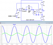
Attached please find a VFA fed back from a pure current source. Turnabout is fair play!
Attachments
forr, this is not an argumentative post. It is an attempt to discover the root of our differences. It may help us all clarify matters if you reply to the following questions.
I think I recall you arguing that since the current through Rf does not flow through the CFA's in (-), this can't be current feedback. If this is incorrect, please say so and disregard the rest of this post.
Consider the case in which in (-) is being fed by the Thevenin equivalent of the standard Vout, Rg, Rf circuit: a voltage source equal to Vout * Rg / (Rg + Rf) in series with a resistor Rfg = Rg || Rf. (The open loop output impedance is neglected here for simplicity, but could be accounted for.)
Surely the same current from the Thevenin voltage source flows through both Rfg and in (-). Can we agree that this can be called current feedback? If not, please say so and disregard the following.
in (-) cannot distinguish between these two circuits. The difference between them is the difference between the outputs and the feedback networks. Am I correct in assuming that this difference is enough for you to declare that the CFA does not employ current feedback?
Attached please find a VFA fed back from a pure current source. Turnabout is fair play!
Yeah... you turned a VFA into a CFA.
In the brevity, CFA source resistances can be typically 50 Ohms, while VFA source resistances can be beyond 20K Ohm. It is considered that values in the parallel combination of Rf and Rg normally fall in between these two values, hence can differentiate a CFA from a VFA. This also leads to the conclusion that Thevenin equivalent resistances (the parallel combination of Rg and Rf) that fall below 50 Ohms turns a CFA into a VFA, and values exceeding 20K Ohm turns a VFA into a CFA.
Insert a capacitor in parallel with Rf of a CFA where Rg is 50 ohm and you will see that CFA don't turn into VFA behaviour.
- Home
- Amplifiers
- Solid State
- Current Feedback Amplifiers, not only a semantic problem?