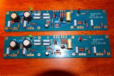
Finished my ALeph J boards
Finished my Aleph J boards, now on to the PSU.
I bought a matched 2SJ74 quad from Spencer at FET Audio | Hi-End Audio Projects when he still sold them quite a while back. They matched perfectly for Idss.
I changed C1 from Wima MKP4 to a Russian military/space/atom grade Polyethylene-Terephthalate (PETP) capacitor OCK73-16B 1uF 63V +/-5%. We'll see how it sounds, and if it is an improvement. Not only does it fit well, it also looks the part with the matte golden colour.
I also used a Nichicon Muse capacitor in position C4, and increased the value of C5 from 5pF to 10pF.
I have a question about the precious 2SJ74 pair: can I put a small piece of shrink tube around them, or is it better not to heat them too much and use a small cable tie-wrap?
Attachments

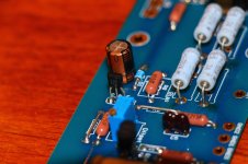
I placed some thermal paste between the JFET's and placed some heatshrink tubing over the pair. Offset is rock stable. It might be over kill, but us Audiophiles are known be somewhat extreme.
Lorado, can I ask where did you buy the Russian 1uF caps from, would be interested in getting hold of some of those.
Ukraine capacitors
I scored them from the Ukraine:
K73-16 CAPACITOR 1uF 63v lot 20 pcs Ussr military soviet audio | eBay
Lorado, can I ask where did you buy the Russian 1uF caps from, would be interested in getting hold of some of those.
I scored them from the Ukraine:
K73-16 CAPACITOR 1uF 63v lot 20 pcs Ussr military soviet audio | eBay
Thanks for the quick reply and the link, cheap as well for this type of military cap. I will have a look at what else he might have.
Hey fellow Oz-diyers, my 5U Deluxe chassis just landed today, so I should be too far behind you.
Guess what's under my ?
?
I've worked to the philosophy for a while now that the best present you get is the one you get for yourself... 😉
Guess what's under my
?I've worked to the philosophy for a while now that the best present you get is the one you get for yourself... 😉
Thanks, so let's validate the whole stuff:R101 10K
R103 100K
R102 10K
R104 100K , put 6p8 to 10p across R104
C101 22uF Elna Silmic , put 1uF solid cap as bypass
also put same bypass across C103
in schematic you show us in post #3212 , just ignore (leave unpopulated) R7 position , and suddenly you'll have proper arrangement

You shall see that I have left R102=100k. If I put R102=10k the gain of the amplifier explodes!
Me, I'm curious of the way it works.
I've checked the models (I'm using the IRFP244 model because it seems that the IRF244 are hard to find) and the load lines are as follows:

So it seems to me that in the "Aleph 3" both devices (upper and lower) cooperates to the output.
This way (on the simulator) I get 33.1W @ 0.018% distortion.
1.82A delivered by the "power supply". 56.5W dissipated by the mosfet (84.7W when idle).
Too good to be true, but encouraging.
I was referencing parts designation from original schm. just remove completely R102 from your sim. For more hard info look in my Babelfish J thread
The amplifier stops working! Amplification factor quite zero!
I get something reasonable if I isolate C101 from the ground, but then the amplifier still doesn't work when used un-balanced.
I get something reasonable if I isolate C101 from the ground, but then the amplifier still doesn't work when used un-balanced.
The schema is the last one. I can send you the (LTSpice) .asc, if you want.
What I expect is that the same circuit will work both with balanced and un-balanced input (apart the amplitude).
Perhaps I've not understood the architecture ...
What I expect is that the same circuit will work both with balanced and un-balanced input (apart the amplitude).
Perhaps I've not understood the architecture ...
Hey fellow Oz-diyers, my 5U Deluxe chassis just landed today, so I should be too far behind you.
Guess what's under my
I've worked to the philosophy for a while now that the best present you get is the one you get for yourself... 😉
Hi Astromo, would you mind telling us how much you paid for postage of the 5U Deluxe chassis to Aussie?
Cheers!
Hi Astromo, would you mind telling us how much you paid for postage of the 5U Deluxe chassis to Aussie?
Cheers!
No worries - shipping came to USD$57.16
The order included:
1 x Riser Panels - 2 pieces of 150mm x 90mm
1 x Riser Panels - 2 pieces of 150mm x 180mm
1 pair of black milled aluminum handles
1 set (4 pieces) of Anti-Vibration feet
The above really didn't count for much in terms of weight / bulk but in the interests of full disclosure, there you go.
For additional info, the above was marked on the con-note as a 16'ish kg shipping weight.
Does that cover it for you?
This works!

Both XLR+ and XLR- "see" the same input impedance.
Now my last problem is that it has too much gain.
With 260mV PP on the balanced side I get 34W with 0.1% distortion.
I need to find the good configuration so that my Audiolab M-DAC+ doesn't overload it (while keeping the same input impedance "seen" by XLR+ and XLR-).
In the service manual I read for the output voltage
4.5Vrms ±0.1 (Balanced)
2.25Vrms ±0.1 (Unbalanced)
Any suggestion?
Thanks
Hello member teodorom,
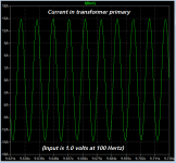
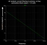
I think you may wish to increase the self inductance of the windings of your simulated transformer "L1 L2 L3". When they are 100 microhenries as shown in post #3237, the simulated currents that flow in the transformer are enormous! Almost ±15 amperes peak to peak, more than 10 amperes RMS at 100 Hz: wow!
I suggest you think about increasing the self inductances by a factor of 1E4 or 1E5, to make the simulated current values smaller and more realistic.
_
Attachments
let's shorten that ......
didn't I told you to look in my Babelfish J thread , or to choose which schematic (original or your sim) I'm going to edit for you .... or asc file ?
that schm will work , but bad
didn't I told you to look in my Babelfish J thread , or to choose which schematic (original or your sim) I'm going to edit for you .... or asc file ?
that schm will work , but bad
Thanks.
I took the input stage from the "Aleph 5" schematics.
I was able to get the appropriate values for the RCA input, but I don't understand what I need to do with the XLR input.
Please consider the resistor values as "tentative".
I took the input stage from the "Aleph 5" schematics.
I was able to get the appropriate values for the RCA input, but I don't understand what I need to do with the XLR input.
Please consider the resistor values as "tentative".
Attachments
- Home
- Amplifiers
- Pass Labs
- Aleph J illustrated build guide