I'm surprised no one wants to try the design challenge. Use the stock 3904/3906 models that come with LTspice and make a 20dB gain line stage from a 20K pot that drives 600 Ohms at 2V rms. To make it simpler just use 19kHz and 20kHz IMD (2V rms total) as the metric. Maybe set a supply current limit of 10mA and allow ideal sources to set up the bias, but real transistors in the signal path. Tracing out where the distortion comes from is a useful exercise.
Why set a supply current limit so low when you're designing with discrete devices? Bonsai's very excellent preamp runs more than 30mA of bias current in the output stage alone. And that's the output stage of every single opamp in his signal path. Why forbid this when talented designers would prefer it?
Or does that negate the VFA/CFA pedagogical value of the exercise?
That's the exercise, it's up to you.
Oh. OK. Well in my original circuit its from the transistor C's and the topology causes their distortion contribution to cancel.
THx-RNMarsh
Last edited:
I think Scott means that one shall create a circuit solution, model it in spice and show the IM distorsion behaviour.
//
//
Oh. OK. Well in my original circuit its from the transistor C's and the topology causes their distortion contribution to cancel.
No FET's, and from a 10K source impedance at audio frequencies unlikely anyway. I don't care about the power budget just keep it equal and sensible. I just thought a diversion from the circular discussion might be good, probably a never mind.
Last edited:
For simple circuits, I can bread-board it as fast as i can pick and place parts and wires on the screen.
I had my circuit still wired and as expected**...from low Z source the thd is .0007% and almost 6 times worse when source is 10K ... .004%
Same thing happens if I add more device C to any transistor... creating a simulated mis-match in device C's........ the thd goes up.
THx-RNMarsh
** all bipolar... non-cascode.
Last edited:
Hi Chris,
We are seemingly very good in miscommunication, but I take full and complete responsibility for that, but don't worry, at the end we solve all this.
Your control over the English language is so much better than mine.
Hans, I take full responsibility for being a typical American, whose language skills are limited to the hopeful mastery of one language only, with a mere dabbling insufficient for proper communication in a second (French, in my case).
Can we agree that DIT requires the availability of a global loop? Because in the absence of such, a "return" voltage is impossible?
If you say that a global loop is not required, I am open to the possibility of an alternative if you are willing to define it.
I think you can explain how they work differently at DC - they are fundamentally not the same.
However, the point made by others is that at DC you do not see in the performance any of the defining characteristics of either topology that you see at HF - namely independence of gain vs closed loop bandwidth (CFA) vs constant gain bandwidth (VFA), or COD (CFA) vs slew limited behaviour (VFA).
There of course is still the small matter of claiming a CFA is a VFA because it still 'compares voltages' at its inputs. However, that's neither here nor there because the voltage at the CFA inverting input requires a current to flow across (Rg + re) to develop a voltage at the - input that equals the non-inverting input (lets assume DC for this immediate discussion to keep it simple) and this current, as Scott has pointed out, can flow into and out of the inverting input. I am afraid no VFA does this - the inverting input impedance in the ideal case is infinite and the feedback resistors can therefore take on a very wide range with little or no effect on performance. In a CFA, if the feedback network (Rf and Rg) absolute values are too high, it ceases to operate.
Manufacturers don't qualify their devices stating that their identification only applies under AC conditions, placing them in the awkward position as to then qualify when such identification actually begins.
There are multiple issues in rejecting DC conditions as relevant to the classification of a device as a CFA or VFA. If a device is classified as a CFA based upon high frequency conditions alone, did it begin as a VFA? If so, under what AC conditions, or otherwise, did it change from being a VFA? Is it a 10% overshoot? Minimum slew rate? What about badly designed CFA's that behave like VFA's?
What is the list of criteria whereupon a VFA under DC conditions becomes properly classified as a CFA, and who is going to be the arbitrator as to agree to it? Secondly, if a device is already classified under DC conditions as a CFA what is the point of proving it continues to be the case under high frequency AC conditions, other than identifying the advantages?
This is not to suggest that the nature of a CFA can't change entirely under low or high frequency conditions, rather that those changes must be a continuation from a DC characterization, otherwise it seems you enter into the quagmire of hopeless spirituality.
We’ve thrashed this thing out for years now. I’ve simply stated that at DC it’s hard to tell the difference other than that a VFA is usually better (bias currents, offset, drift etc) - but for most AC applications it’s neither here nor there because things like bandwidth, settling times, slew rate etc are more important and that’s generally where CFA’s excel.
Absolutely nothing to do with ‘properties changing’ but probably better understood by recognizing that they diverge from DC.
You are being argumentative for the sake of it and this does not progress the discussion.
Last edited:
Scott,I'm surprised no one wants to try the design challenge. Use the stock 3904/3906 models that come with LTspice and make a 20dB gain line stage from a 20K pot that drives 600 Ohms at 2V rms. To make it simpler just use 19kHz and 20kHz IMD (2V rms total) as the metric. Maybe set a supply current limit of 10mA and allow ideal sources to set up the bias, but real transistors in the signal path. Tracing out where the distortion comes from is a useful exercise.
To make a 20dB line stage from a pot is rather cryptic.
Has the 20dB gain to be understood from before the 20k pot, thus to get 2V out you have to feed the pot input with 200mV ?
And can we use an LTSpice voltage source with no serial resistance ?
Hans
Chris,Hans, I take full responsibility for being a typical American, whose language skills are limited to the hopeful mastery of one language only, with a mere dabbling insufficient for proper communication in a second (French, in my case).
Can we agree that DIT requires the availability of a global loop? Because in the absence of such, a "return" voltage is impossible?
If you say that a global loop is not required, I am open to the possibility of an alternative if you are willing to define it.
A global loop is indeed not required for a CFA, quite contrary to a VFA.
Of course this makes only sense in a testing set up.
But, this could even be used as another significant different between the two.
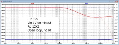
In open loop, when only applying Rg without an Rf, a current equal to Vin/Rg
will flow when offering Vin to the positive input.
Depending on the ratio of Z(s)/Rf, a voltage wil appear at the output of Vin*Z(s)/Rf.
In case of the LT1395 LTSipce is using a Z(s) of ca. 125K//3.5pF.
So for frequencies below 100Khz, gain will be a flat 20 dB when using an Rf of 12k5. See image below.
The same can never be done with a VFA !
Hans
Attachments
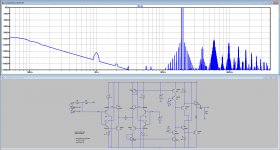
Scott,I'm surprised no one wants to try the design challenge. Use the stock 3904/3906 models that come with LTspice and make a 20dB gain line stage from a 20K pot that drives 600 Ohms at 2V rms. To make it simpler just use 19kHz and 20kHz IMD (2V rms total) as the metric. Maybe set a supply current limit of 10mA and allow ideal sources to set up the bias, but real transistors in the signal path. Tracing out where the distortion comes from is a useful exercise.
can you live with this.
10mA current supply,
Pot are the two resistors R2 and R3, together 20k.
Gain is 20dB.
Load 600 Ohm.
Hans
Attachments
We’ve thrashed this thing out for years now. I’ve simply stated that at DC it’s hard to tell the difference other than that a VFA is usually better (bias currents, offset, drift etc) - but for most AC applications it’s neither here nor there because things like bandwidth, settling times, slew rate etc are more important and that’s generally where CFA’s excel.
Absolutely nothing to do with ‘properties changing’ but probably better understood by recognizing that they diverge from DC.
You are being argumentative for the sake of it and this does not progress the discussion.
To allege someone as "being argumentative for the sake of it" is in itself argumentative behaviour, as nothing prevents you from ceasing to respond to me. Why are you doing it if you are gaining nothing from it? Is it that you can't help but respond for reasons that my dialog is perceived as a challenge to your egocentric self? Where is the argument in that? Are you now going to respond knowingly that it does not progress the discussion to continue, or are you holding yourself up as the arbitrator of all that is good and evil?
Back to the point. I doubt that what I am currently reading around us that DC conditions are being ignored as necessarily irrelevant. Low frequency AC can be indistinguishable from DC as the phase shift begins as being very small. At what frequency or characteristic do you propose we start considering if a CFA is correctly a CFA or by some other means? What is your argument?
Chris,
A global loop is indeed not required for a CFA, quite contrary to a VFA.
Of course this makes only sense in a testing set up.
But, this could even be used as another significant different between the two.
In open loop, when only applying Rg without an Rf, a current equal to Vin/Rg
will flow when offering Vin to the positive input.
Depending on the ratio of Z(s)/Rf, a voltage wil appear at the output of Vin*Z(s)/Rf.
In case of the LT1395 LTSipce is using a Z(s) of ca. 125K//3.5pF.
So for frequencies below 100Khz, gain will be a flat 20 dB when using an Rf of 12k5. See image below.
The same can never be done with a VFA !
Hans
Hans, I think you and I need an interpreter.
Of course what you are saying is true. And it is certainly not news to me; I have done the same on other occasions.
I'll try again.
Without a loop, no return voltage; without a return voltage, no loop gain calculations; without loop gain calculations, you can't do Middlebrook's test.
Yet there may be other ways to achieve your goals in the open loop case. You can still do a current source insertion anywhere you'd like, but there are certain places that a voltage insertion would be useless.
If there is some procedure that you propose for the open loop case, please state it.
Scott,
can you live with this.
10mA current supply,
Thanks for the effort, that was the idea. I was hoping to show that an equivalent CFA does not do significantly better when both are optimized for an audio application, though typically the CFA will have more noise. BTW I suspect LTspice is overly optimistic vs. something actually built on a PC board so this might not as useful as it could. Every little circuit I tried can get down to ppm levels.
Last edited:
Here is my exercise which aimed to establish that CFA and VFA rely on the same fundamental mechanism. I added an ideally Buffered Feedback Amplifier (BFA).
It can be seen that the control is under the input device which receives the feedback voltage on its emitter, be it buffered or not.
Comments wellcome.

It can be seen that the control is under the input device which receives the feedback voltage on its emitter, be it buffered or not.
Comments wellcome.
I was hoping to show that an equivalent CFA does not do significantly better when both are optimized for an audio application, though typically the CFA will have more noise.
You have mentioned this before... noise may be worse. How much worse when opt for audio? And, is it more than a technical issue at line level signals?
For the CMA circuit typical of #1392 or otther?
Both with 10K source?
THx-RNMarsh
Last edited:
"Back to the point. I doubt that what I am currently reading around us that DC conditions are being ignored as necessarily irrelevant. Low frequency AC can be indistinguishable from DC as the phase shift begins as being very small. At what frequency or characteristic do you propose we start considering if a CFA is correctly a CFA or by some other means? What is your argument?"
Its been stated quite a few times that performance at DC is virtually indistinguishable between the two topologies. You put 1 V DC in you get exactly the same Vo for same gains.
That does not make CFA=VFA because the operating mechanisms are not the same - despite what forr thinks - and I made this point a few pages back. Until we all agree on the differences of operation at DC (see forr's latest post for example), I doubt we will see eye to eye at HF where I am quite sure people will roll out current on demand VFA's, H-bridge etc that will simply confound the issue further.
You ask at what frequency does a CFA become a VFA or vice versa? Perhaps the better question is at what loop gain magnitude are the performance characteristics indistinguishable from each other? As you raise the (open) loop gain of the CFA its behaviour in terms of loop gain bandwidth more emulates that of a VFA. The reason this happens is you always have to deal with the output stage phase shift so you have compensate accordingly. The only area where it probably still remains different is in slew rate - it is easier to get higher SR's with CFA's, but it could be argued that is a moot point if you design for 1V/us per peak output volt which is a nice rule of thumb.
In the sx-Amp write up - fig 14 - the compensation design is evolved and you can see how a CFA with moderate loop gains performs in terms of bandwidth, frequency response and slew rate. In distortion terms, it is not as good as a VFA, but ppm distortion levels were not the primary design objectives (the other class A amps all have similar distortion levels BTW - JLH, Pass, Hiraga)
Note, all of my above comments apply to audio power amplifiers - IC amplifiers have fewer restrictions wrt output stage fT, layout parasitics that affect HF performance etc.
forr, If I understand you correctly, you are saying that because the Vbe's are similar, CFA = VFA. At DC - which is what you have put up - I expect the only differences - if any - you will find are related to the loop gain magnitude. Since they are very similar in your analysis, its not surprising that you don't see any difference, or only a small difference.
Although the operating mechanisms are different, the performance characteristics at DC will be similar. Intuitively, this makes sense, because you expect the amplifiers to be linear/accurate.
Current flows out of the inverting input on a CFA - and the magnitude depends on the compensation capacitor value and frequency and that's why using a square wave stimulus will show the differences in operation that you will not see at DC.
In a CFA you develop a voltage across Rg from the current injected into it from the buffer emitter and Rf driven from the output stage. VFA's don't work like that so I don't know how you can make your claim that they are the same i.e. voltage feedback amplifiers.
"Back to the point. I doubt that what I am currently reading around us that DC conditions are being ignored as necessarily irrelevant. Low frequency AC can be indistinguishable from DC as the phase shift begins as being very small. At what frequency or characteristic do you propose we start considering if a CFA is correctly a CFA or by some other means? What is your argument?"
Its been stated quite a few times that performance at DC is virtually indistinguishable between the two topologies. You put 1 V DC in you get exactly the same Vo for same gains. You ask at what frequency does a CFA become a VFA or vice versa? Perhaps the better question is at what loop gain magnitude are the performance characteristics indistinguishable from each other? As you raise the (open) loop gain of the CFA its behaviour in terms of loop gain bandwidth more emulates that of a VFA. These worked very well.
Not all of my above comments apply to audio power amplifiers - IC amplifiers have fewer restrictions wrt output stage fT, layout parasitics that affect HF performance etc.
Thanks Bonsai. In the past I have unwittingly copied, modified and designed combined VFA/CFA amplifiers. The Tiger .01 of many years ago had what was called a triple on the output, being configured as a VFA input with CFA output. This was followed by personal designs with VFA inputs as connected to unity gain CFA's outputs.
My interest is in understanding CFA's and VFA's under all circumstances that particularly includes under low loop gain. This is were differences are most magnified in support of their understanding. Simply because such amplifiers are rare isn't cause to eliminate them from a theoretical perspective.
- Home
- Amplifiers
- Solid State
- Current Feedback Amplifiers, not only a semantic problem?