mmm, even some more capacitance on that rail might change the sound..like the 15kuF low esr cap. We measured the noise but no way to know how less impedance will affect the sound (can only be positive). Still I am a bit worried about the LDOs and surge of current..
Hi Cdsgames,
With 24/7 usage of katana, I think the glue will be exposed to an increasing temp. We cannot assume that the temperature in the device will say isothermic. Now if it is High-density polyethylene, it may soften for sometime; if it is Polyurethane-based it may have a clingy property.
I believe the glue was applied on top of some discrete components; they may contribute to the high surface temp debilitating the cling of the glue. Surface temperature of the components may be above 200 degC. The glue is sandwich in high temp compoents.
We measured the temp Marudo , its always under 55C. Class A opamp stage its always on so thats the max it will be (those caps under the 1000uF are not related to opamp board and they only get heat from bottom opamp stage)
We measured the temp Marudo , its always under 55C. Class A opamp stage its always on so thats the max it will be (those caps under the 1000uF are not related to opamp board and they only get heat from bottom opamp stage)
you mean the surface where the glue is set or the capacitor surface?
If you used the Raytek laser gun, it is not accurate - I don't trust these guns. Now if you touch the black electrolytic capacitor, I know it is beyond 100 deg C even the adjacent components. With entropy and continuos exposure to high temp, that glue will weaken.
It would be nice if in the next release you will use proper reinforcement on this cap.
Hi Marudo
I just used a thermometer on the cap on my setup and it shows 35C. In any case we will look at glue
I just used a thermometer on the cap on my setup and it shows 35C. In any case we will look at glue
Mine came unglued too. The glue seems to stick to the board, but not the capacitor. Surface may not be porous enough?
Mark,
Mine lost its cling to the PCB surface (atop with discrete components). Surface should be rough for it to fuse well.
Now if you touch the black electrolytic capacitor, I know it is beyond 100 deg C...
Can't be as high as 100 deg C. That is the temperature of boiling water. Electrolytic caps mostly aren't rated for that much temp, and it would burn your finger to touch it if it was really that hot. Allo would have to put a protective cover over it to avoid lawsuits from 3rd degree burns of owners that accidentally touched it.
Mine has been running overnight and is at 80-90 deg F. That makes a lot more sense, seems to me.
Last edited:
Hi Marudo
I just used a thermometer on the cap on my setup and it shows 35C. In any case we will look at glue
Heat distribution may not be covered full in the thermometer probe. Reading may not be accurate too. Some portions of the thermometer probe are exposed to air; heat transfer by convection will occur; surface contact area with your subject will be too small, so it may not be a representative measurement of the capacitor's temp nor the discrete components on the PCB where the glue has a direct contact.
Thanks. Hopefully a metal reinforcement.
Can't be as high as 100 deg C. That is the temperature of boiling water. Electrolytic caps mostly aren't rated for that much temp, and it would burn your finger to touch it if it was really that hot. Allo would have to put a protective cover over it to avoid lawsuits from 3rd degree burns of owners that accidentally touched it.
Mine has been running overnight and is at 80-90 deg F. That makes a lot more sense, seems to me.
Hi mark,
The temperature is apparent surface temp. You wont feel it as the heat dissipates in the air via convective heat transfer very fast. This glue will suffer the most as they receive the sudden brute heat energy via conductive heat transfer.
I would say, epoxy based resins are stronger polymers compared to Polyethylene (such as the glue stick). Maybe they may opt for this material or metal reinforcement.
Interesting:
VOLUMIO soundcheck invitation for Hamburg, Germany : Diy Volumio Projects - Page 10
Katana was powered with two PS, ApplePi with three PS !!!
Matt
VOLUMIO soundcheck invitation for Hamburg, Germany : Diy Volumio Projects - Page 10
Katana was powered with two PS, ApplePi with three PS !!!
Matt
Last edited:
Even though Katana is one of the winners , I would suggest taking it with a grain of salt. The amp used is a Elac ea101eq-g (review )
A good effort from Soundcheck team but it might not show the true capability of Katana.
Agree
Matt
Even though Katana is one of the winners , I would suggest taking it with a grain of salt. The amp used is a Elac ea101eq-g (review )
A good effort from Soundcheck team but it might not show the true capability of Katana.
Hans Beekhuyzen reviewed Katana v1.2. I thought the Isolator is v1.2; instead it is labeled as v1.3 in the actual photo. In the website, it is still 1.2.
What is the benefit of using a battery set in powering one of the boards in the stack?
Katana was powered with two PS, ApplePi with three PS !!!
Katana needs at least a modest +-15 and 5v linear supply, and some film caps on the +-15v (~110uf per rail?) to sound its best. With the right interpolation filter it can sound excellent, IMHO. It can be done for maybe around $150, plus a 5v supply for RPi.
Trying to use it with two or even three 5v supplies is almost is garbage by comparison, again IMHO. That may seem a harsh thing to say, but just try the linear solution and see if you don't agree, is all I can say.
What is the benefit of using a battery set in powering one of the boards in the stack?
Not necessary at all, if appropriate linear supplies are used.
Heard that Elac amplifier at the Montreal audio show and did not like it at all... Could have been the room though or speakers, source, etc.... I guess it's hard to tell when it's not your own setup.
Katana needs at least a modest +-15 and 5v linear supply, and some film caps on the +-15v (~110uf per rail?) to sound its best. With the right interpolation filter it can sound excellent, IMHO. It can be done for maybe around $150, plus a 5v supply for RPi.
That means three supplies with the RPi.
Matt
That means three supplies with the RPi.
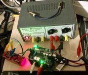
See attached picture for how I did it. That power supply was a $70 kit, and the red thing on the left is some film caps taped together.
There is one more 5v SMPS for RPi, which happens to be an IFI.
Attachments
According to HB sound quality like Chord Mojo?
Linear supplies and film caps together might be better than most people have tried. The combination is very, very good.
- Home
- Vendor's Bazaar
- New FIFO buffer for RPI/SBCs