Sorry I think this is the most stupid question, but RIGHT and LEFT should be used with a GROUND as well, right? So, one cable using ground and LEFT to the left amp input, and the other cable using ground and RIGHT to the right amp input. I have some spare RCA cables I can cut and reuse, if this is correct.
Yup, that is exactly correct!
Following my question above. I can only hear a loud noise, not music. Same noise as if I touch the RCA tip (as if I was the source) but louder. Any suggestion? TIA
Double-check that the orientation of the tda1387 chip is correct (i.e. you didn't accidentally rotate it 180 degrees). I've done that more than once. 🙂
What are you using for your I2S source?
Is it possible to post a picture so I can see if there are any obvious connection problems?
Orientation was ok, I might have f*cked up any other thing though 🙂Yup, that is exactly correct!
Double-check that the orientation of the tda1387 chip is correct (i.e. you didn't accidentally rotate it 180 degrees). I've done that more than once. 🙂
What are you using for your I2S source?
Is it possible to post a picture so I can see if there are any obvious connection problems?
I2S Source is a RPi 2.
I’ll post a pic tomorrow with proper light. In the meantime, it just occurred to me that pins 6/8 (out to amp) that also have the resistor and cap to ground... is this ground the same as the power ground?! I think this ground might go to the RCA cable, not to the common ground from power. If this, it will be an essy fix since i have it in a breadboard. Otherwise I’ll triple check tomorrow while taking the pics
Thank you again!
For this simple experiment, all ground is the same: power ground, tda1387 pin4, RCA ground, I/V resistor ground, etc. You run the risk of a ground loop if you share a ground with the RPI, but I'd say let's first get this thing playing music, then we can clean up grounding issues.
I’m powering the pi with another supply, and only wiring the 3 pins for I2S (1,2,3). So, looks like I have to review the whole wiring tomorrow. Thank you again!
Is it possible to post a picture so I can see if there are any obvious connection problems?
OK not just one but 5, just in case. I know the board implementation is somewhat dirty, I wanted to avoid soldering in this early stage, except for the DAC. I also tested for DAC pins continuity to end of socket pins and all of them seem OK, no shorts, etc.
Details on the passives being used:
C1: 100nF 50v
C2: 220uF 25V
C3: 1000uF 6.3V
C4/C5: 1.5nF 50v
C6/C7: 10uF 250v
R1/R2: 3k
I think I have the wirings OK but I must have something wrong for sure.
Thank you again for the help!


Sorry for the delayed reply!
Thank you for posting pics. I stared at them for a while, and can't see any obvious problems.
First, let's make sure your RPI is setup correctly. What distribution/software are you using? There was some discussion earlier in the thread troubleshooting a similar issue, you can see some tips on that. Also make sure the output device (in Linux) isn't muted and/or doesn't have the volume all the way down. (I'd say put the volume at max, so long as you have a way to control volume on the analog side, e.g. preamp, volume pot, or low-power amp with cheap speakers.)
Next I would power down everything, and do more continuity checking across the circuit. You said you checked between the pins of the tda1387 IC and the socket adapter. Did you check for a short between any tda1387 IC pins?
Next what I would do is check for continuity across the "longest" endpoints. For example, put one meter probe on the ground terminal of your power supply, and the other on pin4 of the tda1387 IC. Keep one probe on the power supply, and then check the ground leads for all the components that have a ground connection. Repeat for positive power supply terminal. Repeat again between RPI GPI pins and tda1387 IC pins (might need a second set of hands to help probe on the bottom of the RPI board since you're hiding the pins on top with your jumper wires).
If all the above checks out, my suspicion would be with the soldering between the tda1387 IC and the socket adapter. It looks OK to me, but see this post, in particular picture/step 05: that was a solder job that also looked OK, but actually wasn't. I've actually done this numerous times with the tda1387 pins (that is, created a bad solder that looked OK, but wasn't; this includes "magical" shorts that I couldn't see but the DMM confirmed was there).
Let us know what you find!
I also tested for DAC pins continuity to end of socket pins and all of them seem OK, no shorts, etc.
Thank you for posting pics. I stared at them for a while, and can't see any obvious problems.
First, let's make sure your RPI is setup correctly. What distribution/software are you using? There was some discussion earlier in the thread troubleshooting a similar issue, you can see some tips on that. Also make sure the output device (in Linux) isn't muted and/or doesn't have the volume all the way down. (I'd say put the volume at max, so long as you have a way to control volume on the analog side, e.g. preamp, volume pot, or low-power amp with cheap speakers.)
Next I would power down everything, and do more continuity checking across the circuit. You said you checked between the pins of the tda1387 IC and the socket adapter. Did you check for a short between any tda1387 IC pins?
Next what I would do is check for continuity across the "longest" endpoints. For example, put one meter probe on the ground terminal of your power supply, and the other on pin4 of the tda1387 IC. Keep one probe on the power supply, and then check the ground leads for all the components that have a ground connection. Repeat for positive power supply terminal. Repeat again between RPI GPI pins and tda1387 IC pins (might need a second set of hands to help probe on the bottom of the RPI board since you're hiding the pins on top with your jumper wires).
If all the above checks out, my suspicion would be with the soldering between the tda1387 IC and the socket adapter. It looks OK to me, but see this post, in particular picture/step 05: that was a solder job that also looked OK, but actually wasn't. I've actually done this numerous times with the tda1387 pins (that is, created a bad solder that looked OK, but wasn't; this includes "magical" shorts that I couldn't see but the DMM confirmed was there).
Let us know what you find!
Sorry for the delayed reply!
Man, no rush at all, c’mon! I really appreciate all the help.
mmm, no the volume is fine cause i’m listening through the headphones as well, but this gave me an idea. I’m usin moode v3, should I choose a DAC from the list or keep it as if there was no DAC at all? I used to have IqAudio but had to remove it once i wanted to try w/o the DAC board. Will try a generic I2S setting tomorrow, essy check.Thank you for posting pics. I stared at them for a while, and can't see any obvious problems.
First, let's make sure your RPI is setup correctly. What distribution/software are you using? There was some discussion earlier in the thread troubleshooting a similar issue, you can see some tips on that. Also make sure the output device (in Linux) isn't muted and/or doesn't have the volume all the way down. (I'd say put the volume at max, so long as you have a way to control volume on the analog side, e.g. preamp, volume pot, or low-power amp with cheap speakers.)
All these are excellent points. The other day I checked and all pins had continuity into the adapter, no Shorts either, but will definitely double check.Next I would power down everything, and do more continuity checking across the circuit. You said you checked between the pins of the tda1387 IC and the socket adapter. Did you check for a short between any tda1387 IC pins?
Next what I would do is check for continuity across the "longest" endpoints. For example, put one meter probe on the ground terminal of your power supply, and the other on pin4 of the tda1387 IC. Keep one probe on the power supply, and then check the ground leads for all the components that have a ground connection. Repeat for positive power supply terminal. Repeat again between RPI GPI pins and tda1387 IC pins (might need a second set of hands to help probe on the bottom of the RPI board since you're hiding the pins on top with your jumper wires).
If all the above checks out, my suspicion would be with the soldering between the tda1387 IC and the socket adapter. It looks OK to me, but see this post, in particular picture/step 05: that was a solder job that also looked OK, but actually wasn't. I've actually done this numerous times with the tda1387 pins (that is, created a bad solder that looked OK, but wasn't; this includes "magical" shorts that I couldn't see but the DMM confirmed was there).
Let us know what you find!
I’ll need more time before I can get my hands dirty, but will for sure keep you posted.
Thank you again!
I’m usin moode v3, should I choose a DAC from the list or keep it as if there was no DAC at all? I used to have IqAudio but had to remove it once i wanted to try w/o the DAC board. Will try a generic I2S setting tomorrow, essy check.
I haven't used Moode, but I can't imagine it's too terribly different from any of the other RPI distros targeted at music playback. I personally use DietPi, but see post #288 above where I described setup for Volumio. I would expect Moode to have similar DAC selection options, you want "HiFiBerry DAC".
OK Matt,
SOLVED! that was it, I had forgot to use a I2S audio device in sound settings, using Hifiberry DAC now. Sound coming from the output and not much background noise (depends on how I hold the cables). Listen:
View attachment sound-tda1387.mp4
So, it's not the best SQ but provided I barely used any decent passives nor an optimized circuit, ...
HOW CAN I MAKE THIS BETTER!? Little giant? Abraxalito's? Yours? I'm thrilled now.
Thank you again for this journey
I'm glad you got it working, and delighted it was a simple fix!
Next step depends on how fancy you want to get.
A small improvement might be to use some "turret board" to re-implement the same circuit. Not sure if "turret board" is the right term, but it's basically perforated wood or fiberglass, where each hole is metal plated. Fundamentally it's the same idea as your current breadboard implementation, but it allows you to pack things much closer together. You have a lot of "antennas" right now with all those long wires looping around.
One of my RPI Hat DACs would likely be the next simplest step. They do require various amounts of SMD soldering, but don't have too many components, and in my obviously biased opinion, sound pretty good (given the simplicity/low cost).
I haven't spent much time on the Little Giant board since originally getting it. But in this and at least one other thread, I've seen people mention a few mods for it that improve it.
Not sure where Abraxalito is at on his DAC... I was under the impression he was working on another major revision, maybe he can chime in.
Other options would be getting and modding the x8 DAC, or the x4 USB DAC, or one of the 8-chip RPI Hats.
Lots of options! But like I said, it all comes down to your goals, budget and desired complexity.
OK I might need to anticipate for some eventual "requirements". I'd like the DAC to:
- have through the hole components (I was OK soldering the IC but never soldered SMD, I have a practise board but it looks too scary to even start)
- have differential output, or even better, both SE and balanced. I understand I'll need two TDA1387 at the very least to cover the differential (I bought 5 of them). I also read Alexander's posts about SE being better due to the fact that balanced removes the 2nd order harmonics. But my power amp is a Modulus86 and needs differential input (even if I can fake it, I guess it's better if it's a real differential)
- the output should be easy to tap somehow, in order to get a headphones out. I have an old Rotel amp I can salvage the HP board from.
Already started to read about the DAC mentioned in your post, but if it's not much abusing your kindness, maybe with these 2-3 "requirements" you have a better idea of what would be best for my case?
Thank you again
... have a practise board but it looks too scary to even start...
There are a number of very instructive youtube videos to teach you how. Just search for 'SMD soldering' or things like that. It turns out to maybe look scary, but pretty easy to do.
There are a number of very instructive youtube videos to teach you how. Just search for 'SMD soldering' or things like that. It turns out to maybe look scary, but pretty easy to do.
I'm watching at
Tangent Tutorial #03: Surface Mount Soldering Techniques on Vimeo
and it definitely does not look so scary... so, OK I'll be brave... maybe I just have 1 requirement left for the DAC now (differential out)?
Last edited:
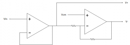
You can do differential out yourself. See attached diagram. Just a couple of dual opamp buffers, one for each channel to do make SE into diff. Resistors could be 5k or 10k, or whatever you think would be suitable, they just need to be the same for unity inverting gain. Vcm can be tied to ground.
Attachments
Last edited:
You can do differential out yourself. See attached diagram. Just a couple of dual opamp buffers, one for each channel to do make SE into diff. Resistors could be 5k or 10k, or whatever you think would be suitable, they just need to be the same for unity inverting gain. Vcm can be tied to ground.
I will study that diagram, thank you.
Also seen this schematics from Peter Daniel for the TDA1543, which has the same pin distribution if I'm not mistaken. This one has no opamp but depends on the use of two DACs to generate the differential signals.
I will study that diagram, thank you.
If you want to read an article on another way, here you go: Versatile, Low-Power, Precision Single-Ended-to-Differential Converter | Analog Devices
Since your power amp will probably need something like this from time to time anyway, you may as well make something you can use when you need it. The first diagram I posted is commonly used in pro audio grear to produce balanced outputs from single ended circuitry. The version at the link above may be a little more fancy.
Personally, the I would just use some low distortion opamps well suited to audio whichever way you prefer. On the other hand, the two dac approach seems a bit much to me, but I guess its yet another choice.
Last edited:
Not sure where Abraxalito is at on his DAC... I was under the impression he was working on another major revision, maybe he can chime in.
Happy to chip in here. The low hanging fruit on a TDA1387 DAC is IME applying some filtering to the 'stair-step' output of the DAC. This is especially a requirement when feeding into downstream opamps (the Modulus-86 amp is opamp based) as opamps seem more susceptible to the high frequency output of the DAC. I recently made a measurement of the raw TDA1387 output which showed spectral lines when playing audio extending up to 11MHz.
With passive I/V normally the resistor value is a little high to arrange an LC after it with commonly available inductor values, but if you're up for sourcing core sets and winding your own inductors, it can be done. Paralleling up DACs would be my suggestion though to allow lower Ls.
In order to create a differential output the route I'd suggest is adding extra DAC chips fed with digitally inverted data. I'd definitely not recommend opamps in the absence of passive filtering upstream. I've been playing over the past month or so with opamp I/V stages and have found none of them so far sounds as good as my lingDAC's discrete stage. The opamp which comes closest to that 'discrete' sound is AD811 and that's a video opamp which runs very warm, quite a far cry from the audio application opamps used in Modulus-86 (for example).
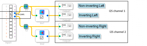
If one wants to go balanced, it is far better to feed +/- channel data into one chip rather than just inverting the data line and feeding that into two different ICs. This can be done with glue logic, or with a DSP (e.g. ADAU1701/sureDSP, which is what I prefer with ICs like TDA1387 since they do not need MCLK). And beside that, imagine what further can be done with the DSP, all that for ~€30 + one programmer. If one wants to go the analog way, I'd recommend using dedicated ICs like TIs DRV135 or THAT 1606/1646 since they have the precision resistors inside to get the needed(?) reasonable CMRR.
Attachments
Last edited:
What makes it better to send the true and inverted data to just one chip? I can imagine its conceptually cleaner to have one IC for L, one for R but why go to all that digital complexity to achieve it? Adding €30 to a couple of €0.02 ICs seems a huge BOM cost uplift to me.
What makes it better to send the true and inverted data to just one chip? I can imagine its conceptually cleaner to have one IC for L, one for R but why go to all that digital complexity to achieve it? Adding €30 to a couple of €0.02 ICs seems a huge BOM cost uplift to me.
Like I said, a DSP comes in handy a lot of times, worth more than the price paid. And its just aesthetically wrong to perform the balancing act in two different chips.
- Home
- Source & Line
- Digital Line Level
- tda1387 dac pcb "front end"