I'm happy to pocket the €30 and accept the aesthetic downgrade. Until I have need of a DSP of course, in which case it'll come for free.
I've been playing over the past month or so with opamp I/V stages and have found none of them so far sounds as good as my lingDAC's discrete stage.
Did you feed it decent power or are you still relying on the heavily coloured LC one? 🙄
So, if I understand you correctly, in order to create a differential output, you propose to:Happy to chip in here. The low hanging fruit on a TDA1387 DAC is IME applying some filtering to the 'stair-step' output of the DAC. This is especially a requirement when feeding into downstream opamps (the Modulus-86 amp is opamp based) as opamps seem more susceptible to the high frequency output of the DAC. I recently made a measurement of the raw TDA1387 output which showed spectral lines when playing audio extending up to 11MHz.
With passive I/V normally the resistor value is a little high to arrange an LC after it with commonly available inductor values, but if you're up for sourcing core sets and winding your own inductors, it can be done. Paralleling up DACs would be my suggestion though to allow lower Ls.
In order to create a differential output the route I'd suggest is adding extra DAC chips fed with digitally inverted data. I'd definitely not recommend opamps in the absence of passive filtering upstream. I've been playing over the past month or so with opamp I/V stages and have found none of them so far sounds as good as my lingDAC's discrete stage. The opamp which comes closest to that 'discrete' sound is AD811 and that's a video opamp which runs very warm, quite a far cry from the audio application opamps used in Modulus-86 (for example).
1. split incoming signal into +/-
2. feed one DAC with + and one DAC with -
3. output passive filter to avoid HF getting into the power amp opamps
If so, I'd be very interested to know the specifics of points 1 and 3. The closest schematics I've seen are those from Peter Daniel for his "balanced" TDA1543, see posts 5 and 6 on his thread.
I am attaching his diagrams for the sake of making comments here easier:


Problem with that receiver/signar splitter is, if I'm not mistaken, CS8412 would not accept I2S.
Thank you again
Last edited:
There's a schematic for my latest TDA1387 implementation on my 'lingDAC' thread. In that I use a 74HC86 in a similar manner to how Peter Daniels has used his 74AC86. But there are a few differences which I'll highlight here.
First, 74ACXX devices are simply way too fast for this application. Speed in CMOS logic brings noise (ground bounce) and noise is one thing we wish to minimize in the digital circuits of a DAC. Hence for best results use a logic family with sufficient speed but no higher, and here that's 74HCXX.
Second, its not necessary to run 74HCXX at the full supply of the DAC chip (6V in my application). Higher supplies for 74HC brings faster speed - here slower is better hence I run the HC86 at 2.5V provided from a TL431. The logic swing needed by the DAC chips is even lower than this so I can't see any downside other than the need to protect the inputs from over-voltage by series resistors. Which would be used anyway by a prudent designer.
Next I run all the I2S signals through the HC86 - this is not just to control noise but also to reduce skew between the various signals. Peter Daniels' implementation of only running data through the AC86 gives him the flexibility to create a switchable inverted option (via the 5k resistor) which I've foregone. Choice of a much faster logic family means his skew is much reduced anyway.
As to point 3 it really does depend how far you wish to go. Are you up for winding your own coils or do you prefer to stick with off the shelf inductors? Also are you up for stacking DACs (means placing them effectively in parallel) to give yourself more output current, hence more flexibility in the filter design?
Downloaded all files, thank you. Will open later or a closer look.There's a schematic for my latest TDA1387 implementation on my 'lingDAC' thread. In that I use a 74HC86 in a similar manner to how Peter Daniels has used his 74AC86. But there are a few differences which I'll highlight here.
OK understood, makes sense to use a slower XOR.First, 74ACXX devices are simply way too fast for this application. Speed in CMOS logic brings noise (ground bounce) and noise is one thing we wish to minimize in the digital circuits of a DAC. Hence for best results use a logic family with sufficient speed but no higher, and here that's 74HCXX.
OK understood, makes sense to feed it less V.Second, its not necessary to run 74HCXX at the full supply of the DAC chip (6V in my application). Higher supplies for 74HC brings faster speed - here slower is better hence I run the HC86 at 2.5V provided from a TL431. The logic swing needed by the DAC chips is even lower than this so I can't see any downside other than the need to protect the inputs from over-voltage by series resistors. Which would be used anyway by a prudent designer.
Here I'm struggling to understand both approaches. I think both aim at reducing skew between signals (why?). In his, he has the "flexibility to create a switchable inverted option" (why?). Sorry for such newbie questions, I really wish to understand better in order to learn.Next I run all the I2S signals through the HC86 - this is not just to control noise but also to reduce skew between the various signals. Peter Daniels' implementation of only running data through the AC86 gives him the flexibility to create a switchable inverted option (via the 5k resistor) which I've foregone. Choice of a much faster logic family means his skew is much reduced anyway.
I will have to wind my inductors around a AA battery for the Modulus86, but they are probably bigger. As for stacking, not really sure what the output current should be, so I don't have a clue for the output stage at all. I gathered info on the amp that might help decide: Input Impedance is 48 kΩ (differential ), Input Sensitivity is 1.8V RMSAs to point 3 it really does depend how far you wish to go. Are you up for winding your own coils or do you prefer to stick with off the shelf inductors? Also are you up for stacking DACs (means placing them effectively in parallel) to give yourself more output current, hence more flexibility in the filter design?
Thank you again for all, I'm really enjoying learning and really appreciate all you guys hand-holding me on the process.
Here I'm struggling to understand both approaches. I think both aim at reducing skew between signals (why?). In his, he has the "flexibility to create a switchable inverted option" (why?).
PD doesn't send the control (CK, WS) signals through the logic. So the data signals will be slightly behind (in time) those control lines. Using an AC86 keeps that excess delay minimal (single digit nS) - hopefully short enough not to impact operation. Using an HC adds significantly more delay so its best to delay all signals the same amount so their relative timings aren't affected. If one got behind others the DAC might not operate correctly.
We can still add in the phase invert function but it means adding a further inverter - either a stand-alone one or a whole extra 14pin package.
I will have to wind my inductors around a AA battery for the Modulus86, but they are probably bigger.
That's an air-cored inductor used for amplifier stability. Its a much lower value (and much higher current capability) than those needed to implement filters. The kind of inductor you'll need will require a gapped ferrite core as using air as the core means far too many turns will be called for.
As for stacking, not really sure what the output current should be, so I don't have a clue for the output stage at all.
Nor do I at this stage but I'm fairly sure that you'll need more than one DAC as the output impedance with a single one in passive I/V is going to be high (say around 3k) and that makes it tricky to implement a filter afterwards.
Of course you do also have the option of going for active I/V - either opamp or a discrete circuit like that used in my lingDAC. If you go this route, a single DAC will be all you need.
I gathered info on the amp that might help decide: Input Impedance is 48 kΩ (differential ), Input Sensitivity is 1.8V RMS
The input sensitivity is presumably a balanced input meaning with two DACs you'll need a full-scale output of 0.9VRMS or 2.5V p-p on each of your two output phases. That's certainly achievable with passive I/V though with a single DAC the output impedance will be 2.5kohm - almost certainly too high for sending to a cable. I'd suggest if you wish to go passive then you go for a minimum 4-high stack of DACs which will give a Zout just over 600ohms. I'll look into whether that's really a practical value to design an LC filter for in the next day or so.
Thank you again for all, I'm really enjoying learning and really appreciate all you guys hand-holding me on the process.
You're welcome.
Got it now, and I think your approach is better.PD doesn't send the control (CK, WS) signals through the logic. So the data signals will be slightly behind (in time) those control lines. Using an AC86 keeps that excess delay minimal (single digit nS) - hopefully short enough not to impact operation.
OK, googled it, and I won't be ready to wind these myself, so I will want to buy whatever is needed.The kind of inductor you'll need will require a gapped ferrite core as using air as the core means far too many turns will be called for.
OK 4 DAC sound good to me, I have 5 of them but can even buy any number, they're the cheapest part of the build I guess.Nor do I at this stage but I'm fairly sure that you'll need more than one DAC as the output impedance with a single one in passive I/V is going to be high (say around 3k) and that makes it tricky to implement a filter afterwards.
(...)
I'd suggest if you wish to go passive then you go for a minimum 4-high stack of DACs which will give a Zout just over 600ohms.
I would really appreciate.I'll look into whether that's really a practical value to design an LC filter for in the next day or so.
So, if I go 4 DACs, which are the VRMS / V p-p on each of the 4 output phases? Would they be 0.45VRMS and 1.25V? In practical terms, what do they mean to the Modulus86?The input sensitivity is presumably a balanced input meaning with two DACs you'll need a full-scale output of 0.9VRMS or 2.5V p-p on each of your two output phases. That's certainly achievable with passive I/V though with a single DAC the output impedance will be 2.5kohm - almost certainly too high for sending to a cable.
I don't discard it yet, since I want to use a headphones out as well, though I might "simply" tap the outputs into the HP board input and add the opamps there exclusively (treat the HP board as the power amp).Of course you do also have the option of going for active I/V - either opamp or a discrete circuit like that used in my lingDAC. If you go this route, a single DAC will be all you need.
...Unless that Zout just over 600ohms mentioned above allows me to drive the HP directly?
Thank you again
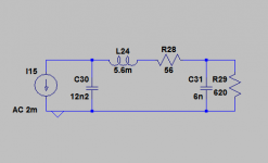
Here's a rough first draft of the filter - I've not factored in yet how the 6n capacitor is created, nor included the specific inductor DCR.
From a quick look on Mouser the best choice for the 5.6mH is going to be Fastron : 07MFG-562J-50 Fastron | Mouser
Your voltage figures look right to me, yes. I'm not sure of the meaning of your next question though - what they mean? They're two anti-phase signals which when combined give the 1.8VRMS required.
A 600ohm Zout isn't going to be useful to feed directly into any kind of headphones, no. Unless your headphones are balanced you'll probably want to convert the DAC's balanced out back to SE.
Attachments
OK I think I'll still need some to to build the digital part of the circuit, so we'll get there.Here's a rough first draft of the filter - I've not factored in yet how the 6n capacitor is created, nor included the specific inductor DCR.
Noted, not so expensive either.From a quick look on Mouser the best choice for the 5.6mH is going to be Fastron : 07MFG-562J-50 Fastron | Mouser
OK, understood now, thank you.Your voltage figures look right to me, yes. I'm not sure of the meaning of your next question though - what they mean? They're two anti-phase signals which when combined give the 1.8VRMS required.
Mmmm there are HPs for 600ohm Zout, maybe not many or not cheap.A 600ohm Zout isn't going to be useful to feed directly into any kind of headphones, no. Unless your headphones are balanced you'll probably want to convert the DAC's balanced out back to SE.
One extra question, where would you add a hardware volume control? I'd want it hardware because if I add a source selection at the input I would miss the volume on the non-RPi source (ie CD transport through S/PDIF). I'm sorry I feel I'm hijacking Matt's thread, but there's so many things to learn! 🙄
One extra question, where would you add a hardware volume control? I'd want it hardware because if I add a source selection at the input I would miss the volume on the non-RPi source (ie CD transport through S/PDIF).
A hardware volume control? There's the option of adjusting the voltage reference of the TDA1387s which certainly gives a hardware volume control though its questionable whether this will provide a level control facility on other digital sources.
How are you intending to route the S/PDIF from a CD transport through to the DACs? Is an S/PDIF input something that can be provided for a RPi? Or are you planning to patch a CS8414 or similar into the I2S stream between RPi and DAC chips? If the latter then varying the Vref (pin7 of TDA1387) is a viable solution.
Hey, this is awesome, I have to try it out, thank you for the idea! Even if I forget about the SPDIF and target this build as a RPi "only" input through I2S, this approach would allow me to have a hardware volume without having to go through ADC plus virtual ALSA mixer, so much easier for sure.A hardware volume control? There's the option of adjusting the voltage reference of the TDA1387s which certainly gives a hardware volume control
Not that I know of. Even if you manage to read SPDIF on the RPi, then you would also need to stream it somehow to MPD so it can be controlled somehow by the same UI as controlling the music coming from a DLNA/NAS. Ideally I'd go this route but I don't think it's doable.Is an S/PDIF input something that can be provided for a RPi?
Yes, I was intending this route, I had a look at AK4113, CS8422 and DIX9211. Then I would have 2 sources of I2S and would just need a 2xI2S input selector (there are many). SO the Vref trick might just do it.How are you intending to route the S/PDIF from a CD transport through to the DACs? Or are you planning to patch a CS8414 or similar into the I2S stream between RPi and DAC chips? If the latter then varying the Vref (pin7 of TDA1387) is a viable solution.
Again sorry to Matt for hijacking the thread. I still think it's all related though. The control of volume directly through the Vref is a nice trick to try out.
Please, don't feel like you are hijacking the thread! IMO, we're all here to learn, and it looks to me like learning is taking place. 
Using pin7/vref as volume control: we've touched on this a bit before... going from memory, isn't the default VREF fairly low, like 1.5v or so? (By "default" I mean using 5v pin5/VDD supply.) Does volume scale predictably with reductions to VREF? How would one go about creating a precise and variable voltage? Seems like you'd need another kind of DAC: not one intended for audio, but simply to convert digital values (volume levels) to voltages (for VREF), presumably with some kind of scaling?
Using pin7/vref as volume control: we've touched on this a bit before... going from memory, isn't the default VREF fairly low, like 1.5v or so? (By "default" I mean using 5v pin5/VDD supply.) Does volume scale predictably with reductions to VREF? How would one go about creating a precise and variable voltage? Seems like you'd need another kind of DAC: not one intended for audio, but simply to convert digital values (volume levels) to voltages (for VREF), presumably with some kind of scaling?
Definitely!Please, don't feel like you are hijacking the thread! IMO, we're all here to learn, and it looks to me like learning is taking place.
 and I really thank all of you for the hand-holding. I feel like I'm coming 5 years late to the party, but I'll get there for sure.
 Yeah, might be doable but I think I'll hit a wall there. One step at a time, I'll leave the hardware volume control for later in the process, at the expense of probably having to rebuild new boards.Using pin7/vref as volume control: we've touched on this a bit before... going from memory, isn't the default VREF fairly low, like 1.5v or so? (By "default" I mean using 5v pin5/VDD supply.) Does volume scale predictably with reductions to VREF? How would one go about creating a precise and variable voltage? Seems like you'd need another kind of DAC: not one intended for audio, but simply to convert digital values (volume levels) to voltages (for VREF), presumably with some kind of scaling?
Now I want to build one of your DACs, Richard/Matt's. Preferably I'll build a 1 chip board + passive HF output (there'll be opamps on the power amp and most likely on a headphones amp as well). Downloaded the all your gerbers, but Eagle is not very intuitive to put it mildly. So I'll need more time to be on track. Will keep you posted.
Definitely!
I still need lots of hand-holding myself. Many here on this site have been very generous with their time to help me learn. I try to pay it back to others as best I can whenever I have the opportunity.
Yeah, might be doable but I think I'll hit a wall there. One step at a time, I'll leave the hardware volume control for later in the process, at the expense of probably having to rebuild new boards.
I've been using software volume control on my RPI DACs. The limitations of doing this are well-known. But you can't beat it for convenience!
Now I want to build one of your DACs, Richard/Matt's. Preferably I'll build a 1 chip board + passive HF output (there'll be opamps on the power amp and most likely on a headphones amp as well). Downloaded the all your gerbers, but Eagle is not very intuitive to put it mildly. So I'll need more time to be on track. Will keep you posted.
I have posted a number of designs in this thread. (Someday I'll try to edit the first post to provide an index for everyone.) But I stopped using Eagle long ago, and am now using KiCad. Only the first one or two designs in this thread were done in Eagle, so if you grabbed one of those, it's likely one of the very early (possibly forgotten/abandoned) designs! I have the parts to build the latest revision of the single-ended RPI HAT DAC, but it will be 2019 before I have the time to actually build and test.
Using pin7/vref as volume control: we've touched on this a bit before... going from memory, isn't the default VREF fairly low, like 1.5v or so? (By "default" I mean using 5v pin5/VDD supply.)
Its 1/6th of the supply voltage, so even lower at 0.833V for 5V supply, 1V for 6V supply.
Does volume scale predictably with reductions to VREF?
I'm fairly sure that it does, trouble is its linear and for volume we ideally want logarithmic law. So some signal processing is in order.
How would one go about creating a precise and variable voltage? Seems like you'd need another kind of DAC: not one intended for audio, but simply to convert digital values (volume levels) to voltages (for VREF), presumably with some kind of scaling?
Interesting idea there - one solution would be a look-up table to convert linear input numbers to logarithmic output, a DAC could certainly work as part of the solution but my first inclination would be to try purely an analog circuit. Only after I reached a dead-end I'd head off in the digital direction.
Does volume scale predictably with reductions to VREF? How would one go about creating a precise and variable voltage? Seems like you'd need another kind of DAC: not one intended for audio, but simply to convert digital values (volume levels) to voltages (for VREF), presumably with some kind of scaling?
That's fairly easy using a MC, ie Arduino. I'll personally stay away from this for the moment.(...)trouble is its linear and for volume we ideally want logarithmic law. So some signal processing is in order.
(...)one solution would be a look-up table to convert linear input numbers to logarithmic output, a DAC could certainly work as part of the solution but my first inclination would be to try purely an analog circuit. Only after I reached a dead-end I'd head off in the digital direction.
I'm trying to go through your designs, guys.I have posted a number of designs in this thread. (Someday I'll try to edit the first post to provide an index for everyone.) But I stopped using Eagle long ago, and am now using KiCad. Only the first one or two designs in this thread were done in Eagle, so if you grabbed one of those, it's likely one of the very early (possibly forgotten/abandoned) designs! I have the parts to build the latest revision of the single-ended RPI HAT DAC, but it will be 2019 before I have the time to actually build and test.
Matt's v2 (8x SE or balanced) looks quite flexible, and uses a passive I/V. I think it does not use the kind of HF filter Richard advocates for in order to avoid HF into the further opamps. If it was an "easy addon" I would go this route. Since the output is passive, it's probably possible to add that HF filter somewhere?
As for Richard's, it's a bit harder for me to understand his 0DAC gerber files from Eagle. Most likely my lack of knowledge/experience looking directly at the board designs, but is there any Gerber importer in Kicad?
Interesting idea there - one solution would be a look-up table to convert linear input numbers to logarithmic output, a DAC could certainly work as part of the solution but my first inclination would be to try purely an analog circuit. Only after I reached a dead-end I'd head off in the digital direction.
I went digital first because I (almost) always assume software-based playback control, i.e. Raspberry Pi (or similar SBC) running MPD. In this case, all control is already digital, so likewise the volume control interface would need to be digital too.
Matt's v2 (8x SE or balanced) looks quite flexible, and uses a passive I/V. I think it does not use the kind of HF filter Richard advocates for in order to avoid HF into the further opamps. If it was an "easy addon" I would go this route. Since the output is passive, it's probably possible to add that HF filter somewhere?
So you're talking about the "front end" boards (the original intent of this thread). I later started focusing almost exclusively on RPI HATs, though a fairly recent design aimed to be a bit of both.
At any rate: the "front end" design intent is to let you use either passive I/V or direct current-out from the TDA1387 chips. The idea is, passive I/V is so trivial, some people may be content with that. And then if you later want a fancier I/V (such as Abraxalito's with the filtering), you can simply use the direct I-out instead of passive I/V.
I'd have to go back and review the design, I can't remember if I put a jumper on the boards for switching between passive I/V and direct I-out... worst-case it might require adding/removing components to close/open the passive I/V circuit.
So as for Z-out and VRMS, it depends on whether you choose single-ended or balanced; how many tda1387 chips you populate; and also if you use passive I/V or direct I-out. And if using passive I/V, those values with further depend on the value chosen for the I/V resistor.
As for Richard's, it's a bit harder for me to understand his 0DAC gerber files from Eagle. Most likely my lack of knowledge/experience looking directly at the board designs, but is there any Gerber importer in Kicad?
I haven't really used it, but I know KiCad has a Gerber viewer. But I'm not sure if you can import to KiCad's native format. Another decent (free) Gerber viewer I've used is ZofzPCB.
Yup, I loved the fact that one can choose different implementations in the same board. 1 chip, 4, 8, SE, "balanced", ... Being a RPi hat is nice, but I value the options a bit higher.So you're talking about the "front end" boards (the original intent of this thread). I later started focusing almost exclusively on RPI HATs, though a fairly recent design aimed to be a bit of both.
I even made a list of DAC design/gerber files shared in this thread, if you think it can be of any value to add in the first post, in newest to oldest order:
TDA Front end v2.0 (gerber, kicad, BOM, schematics)
RPI HAT SE v1.2 (gerber, kicad, BOM, schematics)
TDA Front end v1.0 (BOM)
TDA Front end v1.0 (gerber)
I might have missed more files, and I surely miss the RPi balanced, for instance.
Cool, thank you.At any rate: the "front end" design intent is to let you use either passive I/V or direct current-out from the TDA1387 chips. The idea is, passive I/V is so trivial, some people may be content with that. And then if you later want a fancier I/V (such as Abraxalito's with the filtering), you can simply use the direct I-out instead of passive I/V.
There are legends on the board that indicate what to bridge to get the SE vs Balanced, and Iout vs I/V, if I'm not mistaken. Pretty cool I'd say.I'd have to go back and review the design, I can't remember if I put a jumper on the boards for switching between passive I/V and direct I-out... worst-case it might require adding/removing components to close/open the passive I/V circuit.
Is there a formula/i I can (try to) do the maths from? Otherwise I'd say probably 8x balanced passive I/V, but I don't know about the resistor value.So as for Z-out and VRMS, it depends on whether you choose single-ended or balanced; how many tda1387 chips you populate; and also if you use passive I/V or direct I-out. And if using passive I/V, those values with further depend on the value chosen for the I/V resistor.
Thank you. I found a way to see the gerber from Kicad. If you choose the board app, there is a gerber icon.I haven't really used it, but I know KiCad has a Gerber viewer. But I'm not sure if you can import to KiCad's native format. Another decent (free) Gerber viewer I've used is ZofzPCB.
BTW, the million dollar question, where do you people normally order the PCBs? I'm even considering DIY etching...
Last edited:
- Home
- Source & Line
- Digital Line Level
- tda1387 dac pcb "front end"