SPOOKY LEACH
Hello
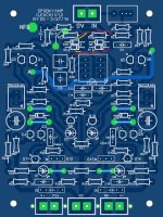
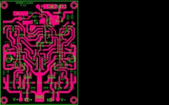
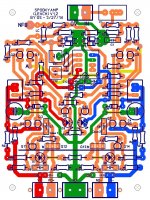
greetings trying to make spooky leach IPS i am following post #1400
along with blue pcb modifications can any one please check if it is
correct on the pink pcb component layout i have posted i have waited
for a long time to make spooky leach at that time components were
not available in my city now i have all the components to make it
warm regards
Andrew
Hello
greetings trying to make spooky leach IPS i am following post #1400
along with blue pcb modifications can any one please check if it is
correct on the pink pcb component layout i have posted i have waited
for a long time to make spooky leach at that time components were
not available in my city now i have all the components to make it
warm regards
Andrew
Attachments
Has there been a consensus on which type sounds better.... CFA or VFA type amplifiers?
Which do you guys prefer after making and listening to so many versions of each.
THx-RNMarsh
Which do you guys prefer after making and listening to so many versions of each.
THx-RNMarsh
Last edited:
From what I've seen CFAs are superior in the high frequency detail and VFAs are the bass kings. Which one sounds better depends on your own tastes and the speakers you are connecting them to. Bi-amping might be the best of both worlds.
From what I've seen CFAs are superior in the high frequency detail and VFAs are the bass kings. Which one sounds better depends on your own tastes and the speakers you are connecting them to. Bi-amping might be the best of both worlds.
Great reply. Thank you.
Actually, I am doing just that --- Bi-Amping a pair of JBL M2's but both drivers with CFA's..
thx-RNMarsh
Last edited:
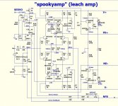
If i remember correctly,Ostripper made 3 versions of Spooky IPS but he preferred version 1.2 over the others. I attach it to compare but i am not 100% sure whether is it the final one or not.
I think this was the input Thimios did some experimenting with and found better results by connecting the servo input ground to the audio input ground instead of G2.
I think CFA is more accurate personally. I'm running a pair of Klipsch monsters with 15" woofers so I don't need any extra help in the bass region in my setup.Great reply. Thank you.
Instead, would you say CFA is more accurate or not?
Actually, I am doing just that --- Bi-Amping a pair of JBL M2's but both drivers with CFA's..
thx-RNMarsh
What are the suggestions for power transistors on the Monster OPS now that Sankens and Semelabs are unobtanium. I can still get 2SC2922 from Digikey, but not it's compliment, which is 2SA1216.
Depressing, really.
Depressing, really.
Newark / Farnell still has lots of stock but their prices have shot up a lot. I'm using MJL4302 / 4281 now. They handle a lot of power but aren't as robust as the Sankens were.
Newark / Farnell still has lots of stock but their prices have shot up a lot. I'm using MJL4302 / 4281 now. They handle a lot of power but aren't as robust as the Sankens were.
Don't see any, but anyway, I have lots of Toshiba 2SA1943/2SC5200 also. Not as nice as the other, but should work.
https://canada.newark.com/allegro-sanken/2sa1295/trans-bipolar-pnp-230v-mt-200/dp/03C3670?st=sanken
https://canada.newark.com/allegro-sanken/2sc3264/transistor-bjt-npn-230vceo-17a/dp/03C3692?st=sanken
The Toshibas will work fine, just lower power handling.
https://canada.newark.com/allegro-sanken/2sc3264/transistor-bjt-npn-230vceo-17a/dp/03C3692?st=sanken
The Toshibas will work fine, just lower power handling.
Thanks for posting something interesting and intelligent (and a lot of work!). Too much nonsense in DIYA just gets depressing. I'm still figuring out the real cost/benefit of each circuit feature, and I have a hard time proving much that isn't "blameless". One thing I don't see much is a low-Z (~50 Ohms)@high freq feedback network, in VFA, which is done in CFAs for other reasons. Every other pole except the dominant pole should be pushed as high as is practical? The GLASUI numbers are impressive but I wonder if that isn't just pushing more gain/feedback? What is the GLASUI phase margin?
Here's the Gerber files for Kypton-ND. The boards are 100 x 76.2mm.
I normally keep these in stock for anyone wanting them. I'm trying to send my last pair to a fellow in the UK but am having terrible luck with the postal service. I'll have more in a few weeks for anyone that wants to build them.
I normally keep these in stock for anyone wanting them. I'm trying to send my last pair to a fellow in the UK but am having terrible luck with the postal service. I'll have more in a few weeks for anyone that wants to build them.
Attachments
hi friend i need power supply, softstart for my slewmonster
Thank you
We have a complete control / protection system that works great with the Slewmaster amps on our website.
Thanks for posting something interesting and intelligent (and a lot of work!). Too much nonsense in DIYA just gets depressing. I'm still figuring out the real cost/benefit of each circuit feature, and I have a hard time proving much that isn't "blameless". One thing I don't see much is a low-Z (~50 Ohms)@high freq feedback network, in VFA, which is done in CFAs for other reasons. Every other pole except the dominant pole should be pushed as high as is practical? The GLASUI numbers are impressive but I wonder if that isn't just pushing more gain/feedback? What is the GLASUI phase margin?
The CFA's low z feedback pushes the poles and unity gain point into the mhz.
No lead compensation and minimal miller is required to retain stability.
The drawback is inferior PSRR (low Z). CFA + an advanced SMPS would
be golden 😀 .
"blameless" and the "sui" , unity gain is several hundred khz. With VFA's ,
you have to battle between usable gain up to 50khz and maintaining >80 degree margin for stability.
Miller capacitance and Cob is much more critical for VFA's.
VFA's are PSRR winners , due to the high Z FB.
Edit - "sui' uses a 2 stage differential for 120db LF gain , harder to keep stable.
It is the one design where I had trouble with stability in the first version.
Sansui used lead compensation to maintain margin in the old 70's design.
ALL the slewmasters are "derated for stability" , with 80+ degree phase margins.
One could use smaller capacitance's to raise unity gain and decrease THD
further. <20ppm @ 20khz and a non-ringing square wave was the design target
for all the slewmasters (cfa or vfa).
OS
Last edited:
From what I've seen CFAs are superior in the high frequency detail and VFAs are the bass kings. Which one sounds better depends on your own tastes and the speakers you are connecting them to. Bi-amping might be the best of both worlds.
I have always suspected that the back EMF of the woofer is more "transparent"
in the low Z feedback of a CFA.
Perhaps the fact that a VFA is more isolated from this affects its performance
in the "bass king" area ?
OS
OS;
What do you think about inverting the middle transistor in your 3EF? ie NPN, PNP,NPN and vise-versa. This can make ~=3EF compatible with Darlington circuits. But I agree that monolithic amps belong at Walmart.
I notice you don't seem concerned with OPS saturation; wasted VPP and heat? I suppose you are not designing 12V automotive amps.
And what about MOS outputs? In my day (~1980) BJTs died a lot so I like MOS SOA. But seems like some linear MOS circuits have no drivers and therefore slew problems? 100mA+ VAS current is not very practical.
Last edited:
- Home
- Amplifiers
- Solid State
- Slewmaster - CFA vs. VFA "Rumble"