Aatto,
I looked already closer to your impedance measurement.
I take the assumption at this moment that for your drivers Mms = 20 g, like mentioned in the datasheet.
Making a model in Leap which impedance fits on your impedance measurement, I have to decrease the BL to 10.5 N/A. In the datasheet BL = 15.5 N/A.
The sensitivity of your drivers is to be expected 3 dB lower than the specification, or 91.5 dB @2.83 Vrms, 1 m.
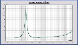
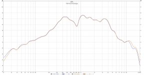
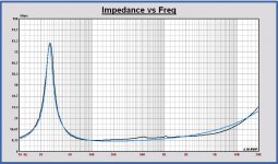
See in plot 1, the impedance of the Leap model (green) and your measurement (black).
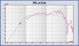
In plot 2, the SPL of the Leap model using the TSP of your measurement (grey) and the SPL of the TD8M datasheet (red). You can see the 3 dB difference and the higher Q impact for lower frequencies.
Without any further comments at this moment, just to inform you, based on your first preliminary measurements.
Only this, maybe trying to do an "added mass" measurement or a calibrated SPL measurement at 2.83 Vrms, 1m on IEC baffle. Then TSP of your drivers can be exactly calculated.
I looked already closer to your impedance measurement.
I take the assumption at this moment that for your drivers Mms = 20 g, like mentioned in the datasheet.
Making a model in Leap which impedance fits on your impedance measurement, I have to decrease the BL to 10.5 N/A. In the datasheet BL = 15.5 N/A.
The sensitivity of your drivers is to be expected 3 dB lower than the specification, or 91.5 dB @2.83 Vrms, 1 m.
See in plot 1, the impedance of the Leap model (green) and your measurement (black).
In plot 2, the SPL of the Leap model using the TSP of your measurement (grey) and the SPL of the TD8M datasheet (red). You can see the 3 dB difference and the higher Q impact for lower frequencies.
Without any further comments at this moment, just to inform you, based on your first preliminary measurements.
Only this, maybe trying to do an "added mass" measurement or a calibrated SPL measurement at 2.83 Vrms, 1m on IEC baffle. Then TSP of your drivers can be exactly calculated.
Attachments
Last edited:
ok, for the burn in, I add a resistor to the amp and play the sine wave frequency (40 Hz for the mids and 15-20Hz for the woofers) and measure the out put, for mids I went with ~6v and for woofers ~10v.
I m gonna let them burn for another day.
for first measurement I had the mic vol wrong 😛.
I do not have a baffle to mount the speakers but I will do between the knees thing that mbrennwa mentioned, both measurements were with the drivers on the table I put the speakers on some silicon pad and some towels for the second one tho, the mids don't have a hole on the back so they don't breath from there.
I will do the measuring with added mass, altho I m gonna use a tape and not a tak putty as I saw in some of the videos, I do not trust that sticky putty not to damage the diaphragm 😀
about the diaphragm measurement, I usually measure from the middle of the rubber surrounding to the other side. I will do it with 155 🙂
and yes I do have the 1k calibrated resistor and I do reset DATS to defaults and re calibrate it every time.
Attached is the Impedance ZMA files, I will do some free air FR measuring soon 🙂
Attachments
the mids don't have a hole on the back so they don't breath from there.
No rear ventilation!? WTF?
I will do the measuring with added mass, altho I m gonna use a tape and not a tak putty as I saw in some of the videos, I do not trust that sticky putty not to damage the diaphragm 😀
I sometimes use a magnet on one side of the cone and a piece of iron on the other side to add some mass.
mbrennwa.
no ventilation on mids or on the woofer, there is this hole on back of the woofer but it looks like 7mm thread hole for dipole maybe, does not look like ventilation, weird, never seen a woofer that big with no ventilation.
I measured the TD15x after 24hrs burning in with 15 to 25Hz sweeps.
the added mass method is weird, I get different results each time, I read about it and everybody say that if you do not add the mass right ( no vibration) you will not get accurate results.
How much mass do you usually add ? is the iron and the magnet have the same weight ?
By the way, the results did not change much since the first time I measured after 12 hours burning, so I either don't doing it right or it's just it.
The ZMAs are attached as well.
Attachments
Last edited:
mbrennwa.
no ventilation on mids or on the woofer, there is this hole on back of the woofer but it looks like 7mm thread hole for dipole maybe, does not look like ventilation, weird, never seen a woofer that big with no ventilation.
That seems strange to me. These are supposed to be high quality drivers, so...?
I measured the TD15x after 24hrs burning in with 15 to 25Hz sweeps.
the added mass method is weird, I get different results each time, I read about it and everybody say that if you do not add the mass right ( no vibration) you will not get accurate results.
How much mass do you usually add ? is the iron and the magnet have the same weight ?
The total weight (magnet + iron piece) is what counts. The weight should be a "good percentage" of the cone mass. 20% or 30% should work ok, maybe also a bit more.
By the way, the results did not change much since the first time I measured after 12 hours burning, so I either don't doing it right or it's just it.
I'd suggest to use a higher drive voltage. I had to beat my Faital woofers quite a bit by running them at 15 Vrms for about 24h. Also remember to cool down the drivers from break in before measuring the impedance curves (a hot driver will have a weak motor and softer suspension than cold).
That seems strange to me. These are supposed to be high quality drivers, so...?
Once this driver isn't focused on PA stuffs, maybe it was designed to play at lower power levels, so the need for ventilations is reduced.
Probably the chassis is optimized to guarantee proper heat dissipation at home cinema level. Aatto could ask AE for clarifications.
Well, since the drivers have phase plugs there won't be ventilation through the back. Same goes for Seas Excel drivers for example.
I measured the TD15x after 24hrs burning in with 15 to 25Hz sweeps.
Out of your first measurement, the TD15X looks close conform specification. fs = 26.3 Hz (spec = 23.2 Hz), Qms = 5.2 (spec = 3.82).
Once this driver isn't focused on PA stuffs, maybe it was designed to play at lower power levels, so the need for ventilations is reduced.
Ventilation helps to reduce mechanical losses. Keeping those low is crucial to get good low-level performance. The PA requirement for ventilation is mostly related to heat dissipation.
Well, since the drivers have phase plugs there won't be ventilation through the back. Same goes for Seas Excel drivers for example.
Oh man, yes, that makes sense! Yet another faceplant moment for me... 🙄
I'd suggest to use a higher drive voltage. I had to beat my Faital woofers quite a bit by running them at 15 Vrms for about 24h. Also remember to cool down the drivers from break in before measuring the impedance curves (a hot driver will have a weak motor and softer suspension than cold).
Out of your first measurement, the TD15X looks close conform specification. fs = 26.3 Hz (spec = 23.2 Hz), Qms = 5.2 (spec = 3.82).
That is good news then Paul, the woofers are taking some serious beating since last night, 15Hz 15v, will do a 30Hz 15v on the mids after that.
Well, since the drivers have phase plugs there won't be ventilation through the back. Same goes for Seas Excel drivers for example.
haha, absolutely, it is front ventilation.
^There is just laminar striction (turbulence) of the coil moving in the gap, practically no pressure variations at all with a plug.
When there is a dustcap moving with the cone, air inside the voice coil former must move too.

When there is a dustcap moving with the cone, air inside the voice coil former must move too.
I read phase plug in woofer mostly helps with heat dispersion, but in tweeters it's different story.
I attached the latest measurements for the TD15Xs, it's after 12 hours of 15Vrms beating, I ll let it burn more but it probably has to wait until next weekend. but numbers are close enough I think.
I also did the first free air FRD measurement as well, it is not ideal since the woofers were on the ground (isolated by isolation pads), the mic was pointing directly at them from above at 60cm from the cone of the speaker ( pointed at side of the phase plug), I brought it down from 1m to avoid some reflection. and please keep in mind that the SPL is not calibrated, so it's just the frequency response. that 800Hz dip is probably reflection from something.
(mic is calibrated USB umik-1).
the TD8Ms are under the load now, 25Hz at 15Vrms, I have to do it in short 2hr sessions since my trusty Accuphase clone amp get really hot when running the mids at low freq.
Attachments

Last edited:
I also did the first free air FRD measurement as well, it is not ideal since the woofers were on the ground (isolated by isolation pads), the mic was pointing directly at them from above at 60cm from the cone of the speaker ( pointed at side of the phase plug), I brought it down from 1m to avoid some reflection. and please keep in mind that the SPL is not calibrated, so it's just the frequency response. that 800Hz dip is probably reflection from something.
You need to mount the driver in a baffle and far away from all reflecting surfaces or objects (floor, ceiling, walls, furniture) for free field measurements.
For low-frequency measurements you might also take near-field measurements with the microphone just a few mm away from the cone / dustcap. This will give useful data in the bass only, where echoes/reflection are masked. But I guess you are mainly interested in bass with these drivers anyway.
Aatto:
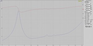
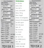
I did a fit again on the measured impedance to make a Leap model of your driver 1.
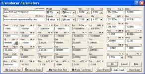
In the plot your driver in black and the Leap model in blue. Also the TSP chart of the model added.
Some differences w.r.t. the datasheet:
fs = 25.8 Hz vs. 23.2 Hz
Qts = 0.37 vs. 0.28
SPL 2.83Vrms = 94.9 dB vs. 96.3 dB (higher Mms and Re, same BL)
We have to review the basreflex system, Qts is too much different.
Have you measured Re separately with an multimeter? Best to do that accurately.
You take a different piston diameter than the datasheet, that one is 330 mm. Best to take the same to compare parameter values. Finally an absolute SPL and impedance measurement should be the reference for the design.
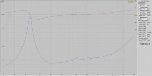
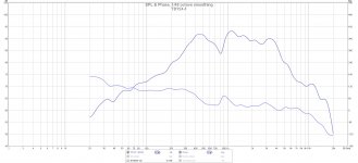
To make a SPL model for a driver I use the TSP of the datasheet or of a measurement at low frequencies up to 400 – 600 Hz and a SPL measurement for the higher frequencies, out of datasheet or other measurement. I used a link of John now to make an expected model for the high frequencies,
AE Speakers TD15X 4ohm - drivervault
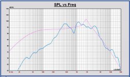
In the SPL plot, your measurement (blue) with the expected SPL (pink), using your measured TSP.
What you see around 300-800 Hz in your SPL measurement, is a dipole behavior of the driver, because there is no baffle. Without a baffle you cannot measure almost anything that makes sense, like Matthias is mentioning also.
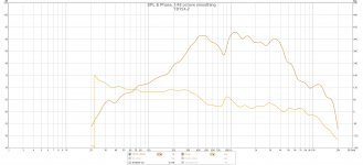
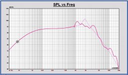
Doing a datasplice at 900 Hz now of the Leap model and your measurement, a very roughly driver model can already be made, see red curve in second SPL plot.
For a good driver model the datasplice should be located around 400 Hz for such size of driver, together with accurate TSP and SPL measurements.
Edit: Aatto, if you measure the SPL later on, please give me also the voltage on the driver and the distance of the microphone to the front side of the driver, that will become flush with the front baffle. Take 2.83 Vrms or some lower value, 1 Vrms for example, if it becomes all too loud.
Also a nearfield measurement will be welcome, its shape is an extra check of the TSP.
I did a fit again on the measured impedance to make a Leap model of your driver 1.
In the plot your driver in black and the Leap model in blue. Also the TSP chart of the model added.
Some differences w.r.t. the datasheet:
fs = 25.8 Hz vs. 23.2 Hz
Qts = 0.37 vs. 0.28
SPL 2.83Vrms = 94.9 dB vs. 96.3 dB (higher Mms and Re, same BL)
We have to review the basreflex system, Qts is too much different.
Have you measured Re separately with an multimeter? Best to do that accurately.
You take a different piston diameter than the datasheet, that one is 330 mm. Best to take the same to compare parameter values. Finally an absolute SPL and impedance measurement should be the reference for the design.
To make a SPL model for a driver I use the TSP of the datasheet or of a measurement at low frequencies up to 400 – 600 Hz and a SPL measurement for the higher frequencies, out of datasheet or other measurement. I used a link of John now to make an expected model for the high frequencies,
AE Speakers TD15X 4ohm - drivervault
In the SPL plot, your measurement (blue) with the expected SPL (pink), using your measured TSP.
What you see around 300-800 Hz in your SPL measurement, is a dipole behavior of the driver, because there is no baffle. Without a baffle you cannot measure almost anything that makes sense, like Matthias is mentioning also.
Doing a datasplice at 900 Hz now of the Leap model and your measurement, a very roughly driver model can already be made, see red curve in second SPL plot.
For a good driver model the datasplice should be located around 400 Hz for such size of driver, together with accurate TSP and SPL measurements.
Edit: Aatto, if you measure the SPL later on, please give me also the voltage on the driver and the distance of the microphone to the front side of the driver, that will become flush with the front baffle. Take 2.83 Vrms or some lower value, 1 Vrms for example, if it becomes all too loud.
Also a nearfield measurement will be welcome, its shape is an extra check of the TSP.
Attachments
Last edited:
Aatto:
For the added mass measurement, I see that you add 188 g, that is a lot on a cone of about 100 g. The recommended value is about 70% of Mms, being 70 gram. That's what I found in some articles.
For the added mass measurement, I see that you add 188 g, that is a lot on a cone of about 100 g. The recommended value is about 70% of Mms, being 70 gram. That's what I found in some articles.
Paul, mbrennwa
in baffle (IEC or anykind of baffle) measurement is not possible for me at the moment. I m not sure but I think we did talk about it, I do not have access to a baffle and building one at the moment is not possible since I may have to move in very near future.
I can do some nearfiled measurements tho.
Is it possible to use initial factory measurements and values for initial design and then measure the rest in intended cabinet ?
as for the T/S parameters, this DATS is weird, I have a calibrated Fluke meter and I get different values than DATS when I measre the Re.
I also used 330mm for diameter before, I m not sure how to actually get the Diameter since I saw different methods and never had to measure one muself before, my main use of DATS was limited to measure the impedance curve.
As for the added mass I used 68g in my first measurement but since my second time measuring I keep getting errors for anything lower than 100g, it keeps saying that the mass is too light and it need to be 25% of ... but the added mass and diameter is only for measuring mms and vas, the rest of T/S parameters is the open air measurement with no added mass, so the different QTS has nothing to do with it and the driver may need more beating ?
Aatto,
We are going to make the best of it. Maybe we can do as follows.
- We assume Mms and Sd to be the same as datasheet.
- Like you say, then we calculate all TSP out of free air impedance measurement.
- Nearfield measurement to check TSP.
- Re measurement with accurate multimeter.
- SPL measurement in cabinet at 1m and if possible SPL calibrated. If you have correct SPL values, Mms can be checked again with high frequency level at a few kHz. And we have also the relative SPL of all drivers.
Edit: we can make an initial design with the assumption of some parameters, maybe already before the cabinet measurements for a first idea.
How did you measure the SPL now, with the microphone on axis? Best to do it that way at a known distance and voltage on the driver.
Then I can use the SPL data above 1 kHz, I think.
Last edited:
Aatto, can you also measure the TD8M SPL like you did with the TD15X?
At about 50 cm on axis from front plate.
At about 50 cm on axis from front plate.
Hey Paul
That is good news.
I will do more measurement, and will also do the TD8Ms, as I said the amp gets really hot with TD8Ms, so I have to do it in short sessions and I do not trust it to leave it over night or when I m not home, I hope to do more measuring today or tomorrow ( the GF is back in town and she doesn't like to share time with my toys 🙁 )
regarding the cabinet, we need a conclusion on tweeter to have accurate cabinet dimensions, so far none of the discussed options give us aligned ACs, I thought about a custom WG, if this was something for my own use I would defiently do that, but with build simplicity in mind and the fact taht the more this continues we will miss interest and potential builders I suggest to make some compromises and go with a ready option.
another problem we have is that if the tweeter fit the available WGs. I can go ahead and see what fits me betetr since i m building this, something that is widely available, and a less headache option, but I like to see others comments first rather than seeing the comments after I made a purchase.
Last edited:
- Home
- Loudspeakers
- Multi-Way
- Open Source "Tower XL"