Yes it is.
CPaul - error amplifiers don't amplify frequency.
Incoherent.
Cpaul - GI,GO.
I don't think so. It may be inherent in low impedance feedback paths.
Cpaul - Demonstrably not so.
No. There is always current fed back.
Cpaul - into a triode grid?
Chris's PLL example is a good one: You control the output frequency but the signal that the error detector uses is actually phase - its not frequency directly. Its called a phase lock loop for a reason
CFA can only be interpreted one way - feedback. If you are controlling current, its a current output amplifier. A practical example would be an industrial 4-20mA transmitter (they used to use millions of them in process control before everything went digital). I have never heard of them being referred to as CFA's.
Another example would be a constant torque drive for a motor - never called CFA or current feedback output - it was always just 'constant current drive'.
seen from the inverting 'CFA' input, that input transistor works in common base, Ie = Ic, that Ic being amplified to form the output current.
I was not clear here. In open loop, there should is no signal for the output entering the feedack network. So made the suppose that a foreign signal is injected in the feedback. Not very important.The input transistor works in common base in open loop.
The main reason why I see the input transistor as not being in common base is that a transistor in common base does not modulate the current across it, the input transistor of a CFA does.
Transmitters and constant torque drives are never called CFAs because they are not called amplifiers. Studying loudspeakers have to distinct the two types of driving, hence the acronyms.CFA can only be interpreted one way - feedback. If you are controlling current, its a current output amplifier. A practical example would be an industrial 4-20mA transmitter (they used to use millions of them in process control before everything went digital). I have never heard of them being referred to as CFA's.
Another example would be a constant torque drive for a motor - never called CFA or current feedback output - it was always just 'constant current drive'.
The input transistor works in common base in open loop.
In close loop, it works like an emitter follower
'As common base in open loop' = contradiction in terminus.
You ignore that the drive comes TO the emitter, from the amp output, through Rf.
Surely you are not implying that the input transistor, as an emitter follower, ultimately drives the output through Rf?
Jan
Why then a CCS and R2 in parallel ? Why should I refer to your unclear schematics as mine were already here and made the most basic as possible. Never mind, I try to anwer your question.Could you answer my questions if you set Rf to zero?
post #726
It is not current which is fed back but the voltage on the emitter of the input stage.what source is the input stage current being fed back from?
post #734
I do not understand "non-bias".Can we agree that for a CFA configured for unity voltage gain (no Rg) that the input stage collector (non-bias) current is substantially the same current that flows (exclusive of any load) from (or into, if you prefer) the output stage?
Am I tired ? I do not see the current in the input stage coming from the output stage. Both currents go in the same direction with a kind of bootstrapping for the input emitter. It is an additive process / positive feedback inside the differential process / negative feedback.And if we add an Rg, that the collector current is the same current as some fraction of that which flows from/into the output stage?
The answer is in the previous paragraph.And that if we restrict ourselves to non-zero and non-infinite impedances, no current or voltage exists without giving rise to the other, and so if a phenomenon can be explained by referring to one, it can also be explained by referring to the other?
In light of this, what forces one to reject as technically incorrect the claim that current is fed from the output stage back to and through the input stage (current feedback)?
Last edited:
Right, I meant "as common base when the amp is an open loop".'As common base in open loop' = contradiction in terminus.
(Refering to CPaul schematics)You ignore that the drive comes TO the emitter, from the amp output, through Rf. Surely you are not implying that the input transistor, as an emitter follower, ultimately drives the output through Rf?
I am implying almost that. Let's first open the loop, Q2 collector disconnected. Let's suppose a positive input voltage. The Q1 emitter by its property of voltage following, replicates this voltage. The Q1 emitter is connected to the output load, so the current inscreases in Q1. Almost the same current in the Q1 emitter passes in the Q1 collector. Let's now close the loop. The base-emitter biased by the voltage drop in R1 due to the collector current of Q1 makes Q2 to deliver current in the load.
The voltage of the input emitter goes in the positive direction, the Vbe of Q1 decreases, and by its propriety of transconductance, this transistor delivers less current to the load, a great part of its initial value is now furnished by Q2. All this is instantaneous.
Is there at any moment a current from the output stage going to the input stage ? No, they converge into the load. The output current of Q2 has an effect on curent in Q1 :
- because, increasing the voltage across the load, it decreases the Vbe and the current of Q1.
- not because a part of it enters Q1 emitter, there is no such part.
Last edited:
You forget that the feedback is negative. The signal current in Rf works in opposite phase to the signal generated by the input signal. It works 'against' it. So it is not the emitter that drives the output, it is the output that drives the emitter.
Also, you can open the loop (delete Rf) and it will still work, because it does not depend on Rf for the forward gain. Rf gives feedback, lowering the gain.
But I will stop this discussion. I do not believe that there is anything in this world that could make you see the light ;-) .
Jan
Also, you can open the loop (delete Rf) and it will still work, because it does not depend on Rf for the forward gain. Rf gives feedback, lowering the gain.
But I will stop this discussion. I do not believe that there is anything in this world that could make you see the light ;-) .
Jan
Forr, It may be more instructive to consider how the currents are behaving in the summing junction to gain an intuitive understanding of the circuits operation. If you are thinking about what happens voltage wise at the emitter of the DB via Rf and Rg, I think you will miss it. Maybe later I can post something up.
Phase and frequency are the same information, one is the derivative of the other.Chris's PLL example is a good one: You control the output frequency but the signal that the error detector uses is actually phase - its not frequency directly. Its called a phase lock loop for a reason
CFA can only be interpreted one way - feedback. If you are controlling current, its a current output amplifier. A practical example would be an industrial 4-20mA transmitter (they used to use millions of them in process control before everything went digital). I have never heard of them being referred to as CFA's.
Another example would be a constant torque drive for a motor - never called CFA or current feedback output - it was always just 'constant current drive'.
The feedback path distinction being debated here is essentially about impedance; when it's high it's being called VFB and when low it's being called CFB. Where is the boundary?
Current and voltage are also related, but’s but more accurate to to separate the controlled quantity at the output from the form that the feedback information takes to describe operation. What would you call a voltage amplifier configured as a current output amplifier? A current output amplifier with current feedback or or a current output amplifier with voltage feedback?
The canonical feedback forms (which have been formalized in academic literature for decades) clearly separate controlled output from feedback form and can be applied equally to both topologies.
The canonical feedback forms (which have been formalized in academic literature for decades) clearly separate controlled output from feedback form and can be applied equally to both topologies.
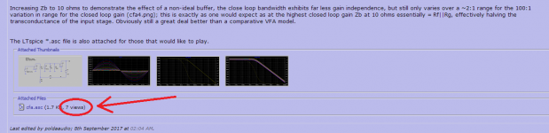
The transition from VFA to CFA is when a change of closed-loop gain (with a classic divider, varying the Rg resistor) starts to affect the OLG which is set by -IN external node impedance.The feedback path distinction being debated here is essentially about impedance; when it's high it's being called VFB and when low it's being called CFB. Where is the boundary?
If you buffer a CFA's -IN or feed it from a very low-Z divider, then OLG set by additional external degeneration R to a constant value, you get a VFA (constant GBW product). The transition to CFA is gradual, that is the transition from constant GBW product to constant BW.
Another way to look at it: The CFA behaviour of constant BW vs gain is not intrinsic, it is set by the feedback network in the classic divider, increasing the gain by decreasing Rg also increases OLG by the about same amount, hence constant closed-loop BW.
If you instead vary Rfb for gain change you get, well.... VFA behaviour once again, as now OLG remains pretty constant.
CFA has one more degree of freedom than VFA: the external node impedance which sets the OLG vs. frequency transfer. OLG in a VFA is fixed unless an uncompensated VFA has extra pins for a external comp cap, that is.
Last edited:
IIRC That was also the point made in one of the earlier references posted. In a VFA, the compensation is fixed (unless pins brought out), usually for unity gain. So you get constant GBW.
In a CFA you can adjust the compensation with Rf for the required closed loop gain, giving you substantially constant BW.
Jan
In a CFA you can adjust the compensation with Rf for the required closed loop gain, giving you substantially constant BW.
Jan
Actually, it is set by Rf//Rg, or more general, the node impedance. I find this point is seldom mentioned explicitly, notably that the impedance change of the classic feedback network during gain change happens to counteract the falling closed loop bandwidth and that this is the sole reason for the (quasi-)constant closed-loop BW vs gain.In a CFA you can adjust the compensation with Rf for the required closed loop gain, giving you substantially constant BW.
For another example of how to make use of the impedance controlling the OLG, if you have a low-Z divider, say, a 47R:47R gain-of-two network, you can short out the stability resistor (say, 1k) with an inductor and get increased OLG at low frequencies from the additional pole and zero (or zero and pole if you look at the impedance).
Last edited:
Give that man a cigar ;-)
Actually another good argument that current feedback is involved. If changing the Rf, Rg values but keeping the ratio the same would not make any difference BW-wise, it would indicate voltage feedback.
Jan
Actually another good argument that current feedback is involved. If changing the Rf, Rg values but keeping the ratio the same would not make any difference BW-wise, it would indicate voltage feedback.
Jan
I'm enjoying this thread 🙂 It appears to me that a CFA will have less phase issues than a VFA and this could be one of it's biggest advantages?
Its also important to note that if you design a CFA (I specifically focus on practical audio amplifiers here) with high open loop gain, and hence high loop gain, the behaviour is much less like a classic CFA with gain-bandwidth independence. The reason is you have to contend with the OPS pole and that then requires MC, TPC or TMC type compensation schemes. So, in these high open loop gain CFA implementations, the wide loop bandwidth in non-MC types is a consequence of the compensation, and not any inherent property of the CFA. If you resort to straight MC compensation (I would not do it with a CFA - no point in my view) on a high loop gain CFA, you get the same pole splitting behaviour you get with a VFA. The OPS pole always has to be reckoned with if you raise the open loop gain - mosfets might give you some wiggle room, but they comer with their own set of issues that still put an upper limit on the ULGF.
The original sx-Amp was a low loop gain/wide loop gain bandwidth (34dB/60 kHz) that only required very light compensation - the OPS pole fell below the ULG minimizing the problems of OPS phase shift.
The original sx-Amp was a low loop gain/wide loop gain bandwidth (34dB/60 kHz) that only required very light compensation - the OPS pole fell below the ULG minimizing the problems of OPS phase shift.
What does the input transistor base drive then ?You forget that the feedback is negative. The signal current in Rf works in opposite phase to the signal generated by the input signal. It works 'against' it. So it is not the emitter that drives the output, it is the output that drives the emitter.
Do not forget that feedback in an amplifier always relies on a voltage difference, CFA included, as CPaul and many others agree in this discussion.
In CPaul's schematics, Rf represents the impedance of the feedback network seen by the input emitter. It is a local feedback, called emitter degeneration, and has a part in the value of the Q1 transconductance.
With today's meaning, a CFA is an amplifier where the feedback network takes part in the value of input stage transconductance, having an effect on the Open Loop Gain and other parameters.
In a CFA, the feedback network works as both local and global feedbacks.
In a VFA, it works only at a global level.
I think we can say that the CF letters refer to the local feedback due to the current from the input emitter into the feedback network.
Last edited:
Why then a CCS and R2 in parallel ? Why should I refer to your unclear schematics as mine were already here and made the most basic as possible. Never mind, I try to answer your question.
The additions of a DC current source and Rf make the circuit "unclear"? Rf is a part of every CFA op amp circuit! And the DC current source allows for greater variability in the selection of the value of Rf.
If this basic configuration is unclear to you, then I begin to understand why we see things so differently.
post #726
It is not current which is fed back but the voltage on the emitter of the input stage.
I will re-word the question. Here is the crux of the post: There is a signal current flowing in the input stage. Currents flow in loops. In a CFA, do you deny that that loop includes the output stage? If so, what is the complete path of that loop?
post #734
I do not understand "non-bias".
The total input stage current is the sum of the signal current and the (DC) bias current. Bias currents ensure that devices operate in the linear region. A typical input stage provides for some sort of DC bias. Non-bias current is therefore the signal current which responds to the voltage signal driving the circuit.
Am I tired ? I do not see the current in the input stage coming from the output stage. Both currents go in the same direction with a kind of bootstrapping for the input emitter. It is an additive process / positive feedback inside the differential process / negative feedback.
The answer is in the previous paragraph.
Wow! We really have a cognitive disconnect between your and my understanding of fundamental electronics!
Please refer to my schematic. AC current flows through the input collector, correct? It must also flow through the associated emitter. It cannot flow through the (DC) current source, which will not pass AC signals. It must flow somewhere. If not through Rf to the output stage, then where does it go?
If you tell me it does not flow through the output stage, then I will bother you no more. It will have become apparent that there is too big a gap to bridge in our understandings of elementary electronics.
- Home
- Amplifiers
- Solid State
- Current Feedback Amplifiers, not only a semantic problem?