If you are using a 220uF cap and 10k resistor per the design, it should take a at least 5 seconds to reach close to working voltage. If you have the diode in backwards, it will come up instantly and not be working as a cap multiplier.
I just ran across this neat looking 0dB buffer from Abraxalito:
https://www.diyaudio.com/forums/dig...e-rbcd-multibit-dac-design-5.html#post5495733
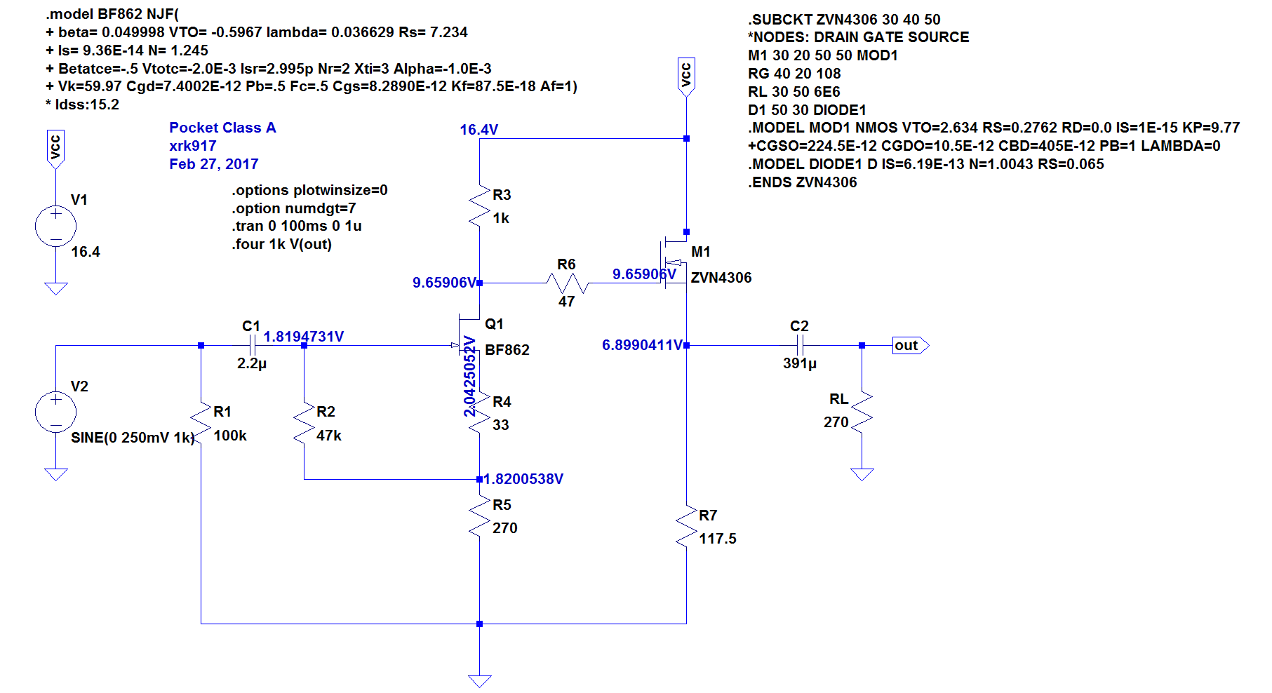
Certainly, a basic MOSFET source follower like what I use for my pocket or desktop Class A amp works quite well too:
xrk971 Desktop Class A (DCA) Headphone Amp
If you want a SE output stage with lower distortion use the output stage of the Aksa Lender preamp (uses a CCS):
AKSA's Lender Preamp with 40Vpp Output
The simplest one is an N-channel MOSFET with a resistive load:
I just ran across this neat looking 0dB buffer from Abraxalito:
https://www.diyaudio.com/forums/dig...e-rbcd-multibit-dac-design-5.html#post5495733
Certainly, a basic MOSFET source follower like what I use for my pocket or desktop Class A amp works quite well too:
xrk971 Desktop Class A (DCA) Headphone Amp
If you want a SE output stage with lower distortion use the output stage of the Aksa Lender preamp (uses a CCS):
AKSA's Lender Preamp with 40Vpp Output
The simplest one is an N-channel MOSFET with a resistive load:
thanks again, XRK. lender's output looks nice. so just input the signal between r12 and r9?
and can i use 24v +/- bipolar PSU instead?
and can i use 24v +/- bipolar PSU instead?
Member
Joined 2009
Paid Member
A symmetrical circuit such as a Diamond buffer may have less turn-on thump but a relay is usually a good idea.
Hi,
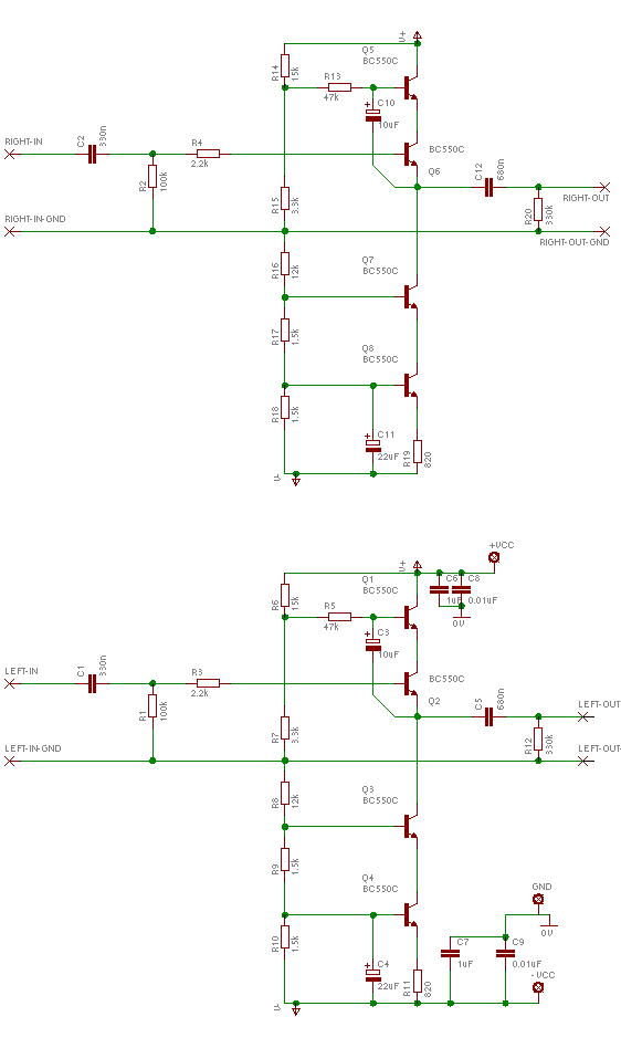
a hybrid Sziklai pair (or hybrid CFP) is a way to very low distortion and considerable drive capability.
The lower half is used as constant current load (trace ´mo´ open) or as a modulated current source (trace ´mo´shorted), ideally allowing for up to twice the load current.
It can be used as SE circuit with a single supply (adding dc-blocking caps) or dc-coupled with symmetrical supply lines.
The Sziklai pair is by far more linear and can drive heavier loads than a typical single small signal transistor.
Adding JFET cascode transistors to the input JFETs will give You a Calvin-Buffer .... a search will give You a lot to read about that little guy´s qualities 😉
jauu
Calvin
Attachments
Yes ive seen your buffer, calvin, and admired it greatly. Its lil too much for my skillset to p2p atm. I could etch a pcb later, tho. Can it be niased class A? And does the output inductor+ resistor have any tradeoffs?
Hi,
the simpler Hybrid CFP variant shown above is not worse compared to the cascoded Calvin Buffer but easier to build.
The cascode just shows very slightly better THD at very low load impedance levels.
Both have to be biased in class-A, because both are singleended in nature.
The output LR-network may be advantageous when driving capacitive loads like long cables, but a resistor alone (with a higher value, say 47Ohms) should suffice in most cases.
jauu
Calvin
Hi,
a hybrid Sziklai pair (or hybrid CFP) is a way to very low distortion and considerable drive capability.
The lower half is used as constant current load (trace ´mo´ open) or as a modulated current source (trace ´mo´shorted), ideally allowing for up to twice the load current.
It can be used as SE circuit with a single supply (adding dc-blocking caps) or dc-coupled with symmetrical supply lines.
The Sziklai pair is by far more linear and can drive heavier loads than a typical single small signal transistor.
Adding JFET cascode transistors to the input JFETs will give You a Calvin-Buffer .... a search will give You a lot to read about that little guy´s qualities 😉
jauu
Calvin
Calvin, Have you tried pch on input and of course nch on #2?
I found it sounded better.
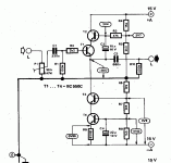
so once again, its this circuit
how can i bias this higher? do i change the bottom resistor 1.5k ohm and the top resistor 15k to lower values?
and is the input resistor necessary if you're not putting a pot before it?
how strong is this buffer btw? im wanting to see if i can drive my sennheiser 600 with it. its 300ohm impedance.
Hi,
You could of course use a Darlington topology instead of single transistors to achieve considerably higher power capabilities.
I´d suggest a CFP (Sziklai) topology as it dosesn´t change the required bias voltages, is easy to stabilize thermally, it´s very linear, and allows for larger voltage swings.
jauu
Calvin
ps. btw. the parts number count of the buffer in #124 is lower than those in #128 and #129 ;-)
Last edited:
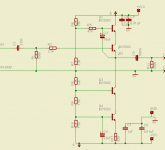
Diamond Buffer with output cascode.
R24 should 100R and R5 500R trimpot.
Calvin, i just really like the sound of the buffer 128. it's very musical which i suspect is because of bootstrap feedback. because of this i'd like to explore the circuit more. no doubt your circuit sounds supreme but positive feedback always holds a magical appeal to me.
Hi,
hey, nothing to excuse for You 😉
I just wondered, because You mentioned that the CFP-Buffer ´d be beyond Your skills .... while it indeed is no more complicated than the other buffers.
jauuu
Calvin
ps. thanks btw. for assuming my buffer to be supreme 😉 🙂
hey, nothing to excuse for You 😉
I just wondered, because You mentioned that the CFP-Buffer ´d be beyond Your skills .... while it indeed is no more complicated than the other buffers.
jauuu
Calvin
ps. thanks btw. for assuming my buffer to be supreme 😉 🙂
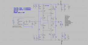
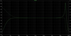
I did an ac analysis for the elector buffer in LTSpice and there is a huge peak in the transfer function.how can this be cured?
Attachments
Last edited:
I did an ac analysis for the elector buffer in LTSpice and there is a huge peak in the transfer function.how can this be cured?
Add bandwidth limiting at the cascode transistor.
Attachments
Member
Joined 2009
Paid Member
how strong is this buffer btw? im wanting to see if i can drive my sennheiser 600 with it. its 300ohm impedance.
Theoretically speaking, the distortion will climb as the buffer finds it has to drive a lower impedance, even 300 Ohm is more trouble than if using the buffer as a pre-amp driving the input stage of a power amp. But doesn't mean that it won't sound very good. So did you try this yet ?
Add bandwidth limiting at the cascode transistor.
bimo, would it be possible to see that in jpeg format? i can't open that file. thank you.
bimo, would it be possible to see that in jpeg format? i can't open that file. thank you.
Attachments
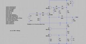
Hi,
did You consider using LEDs (red) instead of R11, R12 and couple them thermally to the NPNs to achieve higher thermal stability of the ccs?
And in using one of the LEDs as kind of preregulator for the second LED the ccs achieved far higher dynamic output impedance.
jauu
Calvin
did You consider using LEDs (red) instead of R11, R12 and couple them thermally to the NPNs to achieve higher thermal stability of the ccs?
And in using one of the LEDs as kind of preregulator for the second LED the ccs achieved far higher dynamic output impedance.
jauu
Calvin
so once again, its this circuit
how can i bias this higher? do i change the bottom resistor 1.5k ohm and the top resistor 15k to lower values?
and is the input resistor necessary if you're not putting a pot before it?
um, i'd like to ask again, how can i bias this circuit higher? just change all the resistors to lower value?
- Status
- Not open for further replies.
- Home
- Source & Line
- Analog Line Level
- Simple discrete unity gain buffer