LOL, why's it so much for a Chinese SC PSU? They must contain magic.
I think they think foreigners are richer, so the price are especially expensive on English websites.
Sharing ultra capacitor power supply PCB
I designed this ultra capacitor explore PCB a couple of months ago. The sound quality was really amazing.
I still have 5 of the bare PCBs available for sharing. If anybody is interested in trying the ultra capacitor power supply by yourself, please PM me your shipping address. I'll send one to you for free.

UCPi_UltraCapacitorExploreBoard_1 by Ian, on Flickr
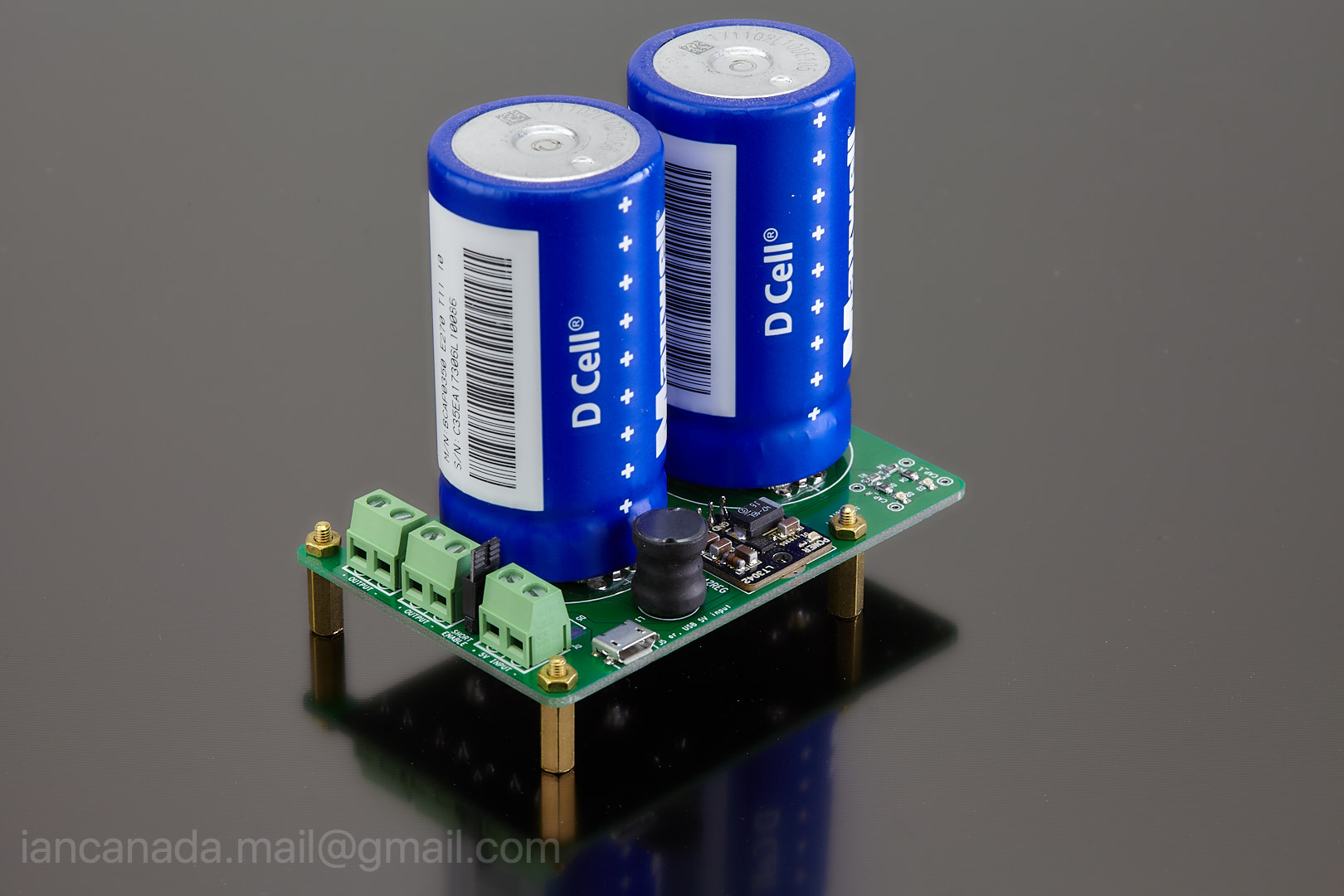
UCPi by Ian, on Flickr
Ian
I designed this ultra capacitor explore PCB a couple of months ago. The sound quality was really amazing.
I still have 5 of the bare PCBs available for sharing. If anybody is interested in trying the ultra capacitor power supply by yourself, please PM me your shipping address. I'll send one to you for free.
UCPi_UltraCapacitorExploreBoard_1 by Ian, on Flickr
UCPi by Ian, on Flickr
Ian
Ian, this is great stuff
I was just asking in the other big forum tread on the power options, and ran into this. It is very clear that the pace of Ian crunching new cool stuff is much faster than my pace of reading diyaudio forums 🙂
Couple of questions;
1) What would be the ideal way of using the battery pack to power Raspberry Pi -> McFIFO -> McDualXO -> Buffalo iii pro -> Mercury setup, would I need 2 of these boards?
2) Is there any advantage of using different 3.3V outputs for different power supplies (e.g. for McDualXO, 1st one for Driver Reg, 2nd one for XO Reg, 3rd one for Reclock Reg) While this requires more number of 3.3V output rails and more battery boards as such, it is costly and expensive, I am wondering what would be the benefits
3) What is the typical charging time of the batteries?
Thanks!
@syracuze)
Couple of questions;
1) What would be the ideal way of using the battery pack to power Raspberry Pi -> McFIFO -> McDualXO -> Buffalo iii pro -> Mercury setup, would I need
2 of these boards?
You can use only one LifePO4 power supply for this application. As same as what I did. To make use of pure battery power, you can remove and bypass all 3.3V LDOs on BuffaloIII.
2) Is there any advantage of using different 3.3V outputs for different power supplies (e.g. for McDualXO, 1st one for Driver Reg, 2nd one for XO Reg, 3rd one for Reclock Reg) While this requires more number of 3.3V output rails and more battery boards as such, it is costly and expensive, I am wondering what would be the benefits
Since the output impedance of LifePO4 batteries is very low. So, theoretically it doesn't make that big difference. However it would be more perfect if you can run each 3.3V rail by independent battery. In this case, 2 LifePO4 power supplies will be required. But I don't think the overall cost will be higher than other high quality power supplies because there is no longer any transformer, big capacitor and regulator in system.
3) What is the typical charging time of the batteries?
My charger is capable for 10A. However to work with standard DC adapter, I'll limit the max charging current to 5A. It normally takes less than 5 hours to charge them from fully empty. However for daily use, it normally takes half to one hour according to my real test. You will not feel it if you always connect the DC adapter.
Regards,
Ian
Thanks for the comments Ian!
I have seen that you have the new v2.0 pcb boards arrived, how are the tests going so far? Do you have an estimate on when this product will be available?
I have seen that you have the new v2.0 pcb boards arrived, how are the tests going so far? Do you have an estimate on when this product will be available?
@syracuze
Hopefully next month if everything is OK. Assembling and prototyping almost done. I'll test it this weekend.
Regards,
Ian
Hopefully next month if everything is OK. Assembling and prototyping almost done. I'll test it this weekend.
Regards,
Ian
1. LifePO4 and ultra capacitor are much better power supplies for DAC and I/V stage than any active regulator with feedback. You can google the principle;
2. Any regulator or LDO after LifePO4 or ultra capacitor will degrade the power supply performance;
3. Floating charging has two problems here:One is that the battery or ultra capacitor will work as decoupling capacitor in this case, they will switch between charging and dis-charging rapidly for dynamic load current demand. Switching between two states will cause ripple thus add noise to voltage rails. The other problem was mentioned above, yes, it's the isolation.
Regards,
Ian
Ian, is there any good reading material that you can direct me?
I am keen to learn the differences between active regulation and passive power supplies. I googled a bit, but could not find much information, appreciate any pointers.
Hi Ian
Been thinking about implementing your ps into my SDTrans sd card player but Im trying to wrap my head on how it can be done. Reason there’s 3 3.3v supply which is cover by your ps but the headache part is theres 2 5v supply for the LCD display & SD card reader as well as a 1.2v & a 2.5v rail which supplies the FPGA chip. On the FPGA chip I guess I still need to keep the regs intact & perhaps use your super cap board to power the lcd & sd card reader.
Question : How can we keep all this in syn ?
Thks again Ian
Fully assembled LifePO4Pure V2.0 PCB except the batteries. I was very busy this weekend. Will do a functional test is a day or two.
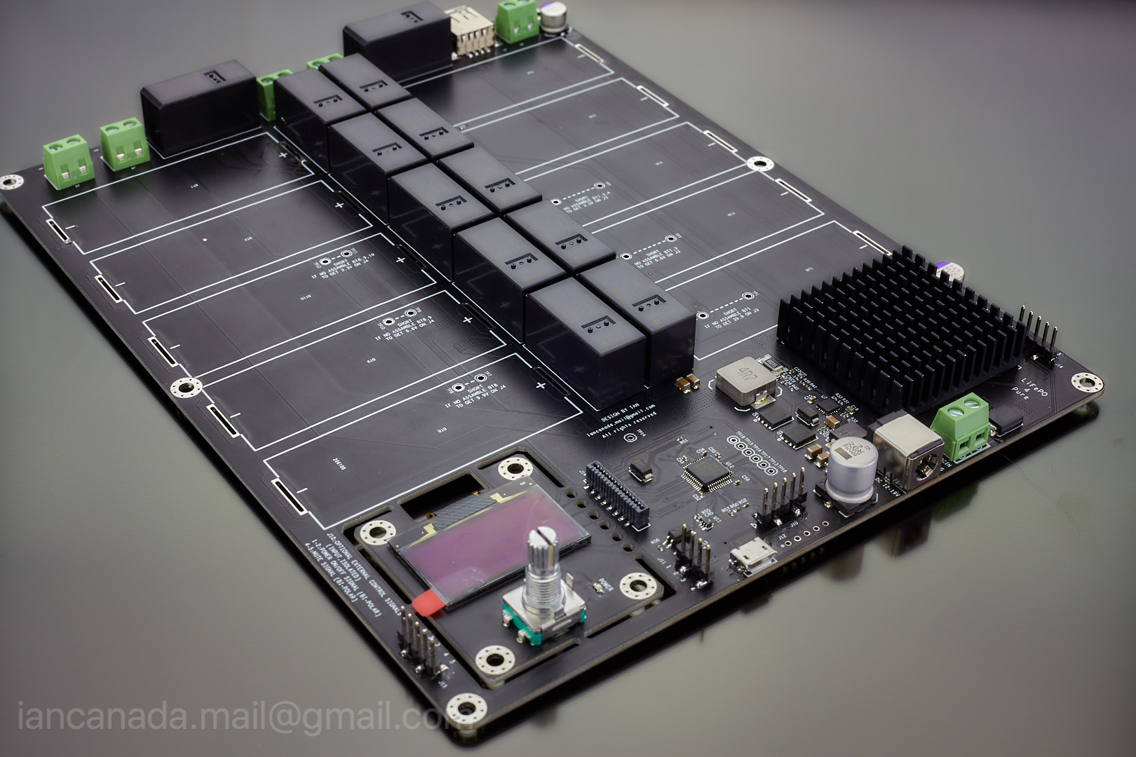
LifePO4PureV2.0_1 by Ian, on Flickr
Ian
LifePO4PureV2.0_1 by Ian, on Flickr
Ian
Fully assembled LifePO4Pure V2.0 PCB except the batteries. I was very busy this weekend. Will do a functional test is a day or two.
LifePO4PureV2.0_1 by Ian, on Flickr
Ian
What a beauty Ian. Congratulations!
- Home
- Amplifiers
- Power Supplies
- Develop ultra capacitor power supply and LiFePO4 battery power supply