Ok, next question 🙂 Thanks again in advance!
I'd like to know if the resistor I ordered for R21 is correct and the LED. It looks like I ordered a 10K 1/4w MINI (somehow a mini). The LED I got is a 2V 10ma.
Will that work?
If you can answer the bigger question - How do you figure out the optimal resistor value so it's something I can calculate on my own moving forward? I think I can use ohm's law to calculate the value if I knew the volts and amps going into the resistor.
There is a resistor and an LED on the left / right channel board that I need to populate also and would like to try to figure it out rather than ask. Now that I think of it, I might have ordered the 10k resistor for this and not the PSU.
Thanks,
Kevin
Attachments
it is L bracket , fastened to base plate ........ nothing to have with front plate
Thanks for the tip. I couldn't spot that bit of hardware detail in the photo.
Hi Kevin,
Your 10K resistor will work for your LED.
Resistor for LED >> Resistor Guide
The resistor is to limit the current to the LED so it's not too bright/blow up, etc.
Your LED is 2V 10mA so expect the LED voltage drop to be about 2V.
In your standard FW power supply, each rail is at say about 25V. So if you
drop 2 volts across the LED, you're left with about 23V.
How 23V across your 10K resistor means 2.3mA, so that's the current going
through your LED. The exact current isn't important so long as it's too
too high to damage the LED or too bright to annoy you. (And 2.3mA is
certainly lower than 10mA so it's safe.)
Now the resistor power rating: You have 23V across the resistor. From Ohm's
law, P=VI = 23V x 2.3 mA < 0.06W < 0.25W. So you have good
safety margin there. (You don't want to run a resistor close to its power rating.)
Hope this helps.
Dennis
Last edited:
Perfect, thank you.
My 4U chassis is in transit and I’ll be assembling it all soon, slowly. It’s a big leap from the ACA to thie F5 for a noob with no electronics experience, but after a few months of digesting all this stuff, I think I can do this.
My 4U chassis is in transit and I’ll be assembling it all soon, slowly. It’s a big leap from the ACA to thie F5 for a noob with no electronics experience, but after a few months of digesting all this stuff, I think I can do this.
Just ask questions if you're unsure and I'm sure you'll be fine.
The F5 is reputedly more accurate than the ACA so it should make for an
interesting comparison.
(Hmmm...perhaps I should build an F5 also... 🙂 )
The F5 is reputedly more accurate than the ACA so it should make for an
interesting comparison.
(Hmmm...perhaps I should build an F5 also... 🙂 )
How can I tell which side is positive or negative for the LED on the PCB?
On the other few things I’ve built, I’ve seen a square or circle around each hole indicating polarity, a flat mark on the circle, or even + or - signs. This one does not seem to show anything remarkable.
Im guessing it’s just common sense that the current flow is going from one side to the other....
Thanks
Kevin
Attachments

Hi Kevin,
Referencing the PS PCB schematics:
https://cdn.shopify.com/s/files/1/1006/5046/files/P-PSU-1V30-schematic.pdf
You can see that:
- the cathode (short) leg of the LED3 connects to R21.
- the anode (long) leg of LED2 connects to R20.
(Some info on LED here:
Polarity - learn.sparkfun.com )
Hope this helps.
Dennis
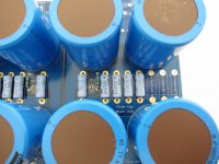
Made lots of progress building up the boards, the PSU and the case. But I have the next challenge.
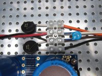
Attached is the photo from the build guide. The second photo is the diagram from my transformer, the Antek 4218.
The primaries are in Red / Black pairs. I’ve tested them to verify which are the pairs. The first pair I’ll call Red 1 / Black 2 - second pair is Red 3 / Black 4.
From the build guide photo - if I knew which colors where paired with each other, I could wire mine to match, but I do not.
Is it as simple as inserting my named wires into the terminal block, from top to bottom, 1 - 2 - 3 - 4 ?
Thanks again !
Attachments

Thank you! I see it now.
I was using the new build guide plus the PDF guide, forgot there is the beginning of this thread also.
I was using the new build guide plus the PDF guide, forgot there is the beginning of this thread also.
Hey folks. Just finished my F5 clone... have 2 quick questions, i am sure someone will know the answers..
1. What is the power supply voltage when the amp is turned on? I have 2x18V on the transformer (DIY 500VA) and using 2x 5A graetz with filtering (8*15.000) but i have only +-20V when i measure it while the amp is turned on.
2. I can not set the bias on one of the channels to higher than 0.1V.. The other channel is 0.6 so it's fine.. What can be the problem?
Otherwise the amp sounds great even with 0.1V on one side...
Thanx for the answers!
1. 18Vac secondaries.... it's normal to see around 22Vdc or so at rails , with regular FW arrangement PSU ; check sec. voltages under load
2. pictures, pretty please ; check resistor values around TL431
2. pictures, pretty please ; check resistor values around TL431
I can not set the bias on one of the channels to higher than 0.1V.. The other channel is 0.6 so it's fine.. What can be the problem?
I had that same problem when I built my F5. I change R3 and R4 to 4.7K and it biased up just fine.
you got me there 🙂
probably had opened F4 related one ...... cats and dog constantly jumping on my lap aren't helping .......... in fact - they're helping , but not in replying 🙂
probably had opened F4 related one ...... cats and dog constantly jumping on my lap aren't helping .......... in fact - they're helping , but not in replying 🙂
you got me there 🙂
I did? The Mighty Zen Mod...how can that be. You must need some sleep.😴
Are you sure R3 and R4? They are marked as 10 ohm resistors in the schematic, changing them to 4.7k sounds a big difference to me.ZM this is an F5 thread😕
Oh, just figured out, maybe you were referring the schematic from the original manual.. In that case it's the two resistors 2.2k which are in parallel with the bias setter potentiometers? That would make more sense... 🙂 Thanx for the tip.
Oh, just figured out, maybe you were referring the schematic from the original manual.. In that case it's the two resistors 2.2k which are in parallel with the bias setter potentiometers? That would make more sense... 🙂 Thanx for the tip.
That’s correct it was the original schematic. I’m not familiar with newer iterations. Yes it would be the resistors in parallel to the pot, I know them as R3 and R4 but whatever they are now if you change them from 2.2K to 4.7K you sound be able to bias at 1V which I believe is spec.
Edit: Maybe spec is .6V I can’t remember.
Last edited:
- Home
- Amplifiers
- Pass Labs
- An illustrated guide to building an F5