Well after finding some 3 amp 125v slow blow fuses, the PSU powers up for about a second or two before one fuse blows. When measuring the voltage out of the PSU at V+ and GND with my DMM per the manual instructions, it gets to about 5 volts out before the fuse blows. The LED lights light up but not very bright and the voltage slowly bleeds out.
I don't have either of the channels hooked up to the PSU so there is no load.
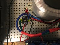
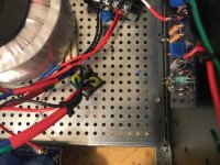
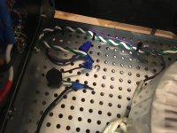
Here are some pics of everything on the way to the PSU.
The only couple things I'm unsure about are the secondary wires into the rectifier blocks. The DC out are + and - but I wasn't totally sure if the blue / green wires were on the right ones or if it even mattered. The other was the purple wire from the transformer. The guide said to connect it to ground or cap it off. I tried both and the fuses still blew.
If this all looks good then perhaps it's something on the PSU.
I was feeling real good about powering it up today so I'm bummed it didn't work as planned.....
I don't have either of the channels hooked up to the PSU so there is no load.
Here are some pics of everything on the way to the PSU.
The only couple things I'm unsure about are the secondary wires into the rectifier blocks. The DC out are + and - but I wasn't totally sure if the blue / green wires were on the right ones or if it even mattered. The other was the purple wire from the transformer. The guide said to connect it to ground or cap it off. I tried both and the fuses still blew.
If this all looks good then perhaps it's something on the PSU.
I was feeling real good about powering it up today so I'm bummed it didn't work as planned.....
Attachments
Your secondaries on the transformer may not be correctly wired.
There are two windings (secondaries) on the transformer. They create a "loop". You may have one secondary wire from one winding, and the other secondary wire from the other.
You can test for secondary "pairs" of wires with a meter. The green and blue wire that are a pair will have a lower resistance (not zero, but lower) than a mismatched pair. This is how you know which wires are a pair. Two wires that are not a pair will show a lot of resistance.
Rectifier blocks could be miswired as well but I can't see enough in the pics. On the blocks the corner with the little notch in it is positive. Also, you don't need the electrically isolate those rectifier blocks. They are isolated.
The purple wire is a electromagnetic shield for the transformer to prevent noise/interference. It is connected to foil shielding around the transformer. It has no effect other than that. You can hook it back up.
Make sure variable resistors, P1 and P2 an each board are adjusted to zero ohms before applying power. Ignore any instructions that say "turn fully clockwise" or "counterclockwise", since these instructions can be misleading, depending on how you installed the trim pots.
Make sure variable resistors, P1 and P2 an each board are adjusted to zero ohms before applying power. Ignore any instructions that say "turn fully clockwise" or "counterclockwise", since these instructions can be misleading, depending on how you installed the trim pots.
Yep, my trimpots go to zero ohms turning clockwise, opposite of the build guide.
Your secondaries on the transformer may not be correctly wired.
There are two windings (secondaries) on the transformer. They create a "loop". You may have one secondary wire from one winding, and the other secondary wire from the other.
You can test for secondary "pairs" of wires with a meter. The green and blue wire that are a pair will have a lower resistance (not zero, but lower) than a mismatched pair. This is how you know which wires are a pair. Two wires that are not a pair will show a lot of resistance.
Rectifier blocks could be miswired as well but I can't see enough in the pics. On the blocks the corner with the little notch in it is positive. Also, you don't need the electrically isolate those rectifier blocks. They are isolated.
The purple wire is a electromagnetic shield for the transformer to prevent noise/interference. It is connected to foil shielding around the transformer. It has no effect other than that. You can hook it back up.
Thanks, I think this is what it might be. I retested the primaries to verify I’m using the correct pairs - they are correct. I tested the secondaries - my pairs show no resistance. When I try the wire from the other “pair” I get something barely more than zero.
So I’ll try switching them around and see if that works and report back.
Yep, my trimpots go to zero ohms turning clockwise, opposite of the build guide.
Yes. So the safe thing to do before power up is to adjust P1 and P2 so that
the measured resistance values across R5 and R6 are low.
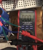
Actually none of my secondary pairs show lots of resistance. It’s either nothing or just barely more than nothing.
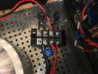
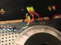
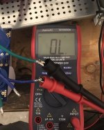
First pic is the original pair I put into one rectifier block.
Second pic is when I swap out the green wire.
Would the first picture be the pair or the second?
First pic is the original pair I put into one rectifier block.
Second pic is when I swap out the green wire.
Would the first picture be the pair or the second?
Attachments
I think typically the Antek secondaries are in "in order" as constructed, so you might follow the wires back to the donut and try that. See also MJ's "phase dot" device and description. But would such (mis) wiring really cause fuses to blow?
BK
BK
Mrshazbot - Select the "Beep" function for continuity. The secondary leads will beep if they are from the same pair.
Also PLEASE disconnect the amplifier boards from the PSU!! If the PSU isnt working, why do you want to risk your amp boards? 😕😕😀
Astromo - Its a capacitor for filtering high frequency of the mains. The suggested capacitor is 0.0033uF (3300 PICOFarad), X2/Y2 rated, which are all rated 250VAC, and are designed to be put across 240v mains.
Suggested value does not change with 120 or 240v mains.
Yes
Also PLEASE disconnect the amplifier boards from the PSU!! If the PSU isnt working, why do you want to risk your amp boards? 😕😕😀
Astromo - Its a capacitor for filtering high frequency of the mains. The suggested capacitor is 0.0033uF (3300 PICOFarad), X2/Y2 rated, which are all rated 250VAC, and are designed to be put across 240v mains.
Suggested value does not change with 120 or 240v mains.
But would such (mis) wiring really cause fuses to blow?
Yes
Thanks, the beep function says I was originally using the wrong pairs.
Thankfully, the only smart thing I might have done so far was to not connect the amps or else they would probably have been fried. I actually had a dream last night that I did fry them so my level of obsession on getting this working is probably approaching unhealthy.
Thankfully, the only smart thing I might have done so far was to not connect the amps or else they would probably have been fried. I actually had a dream last night that I did fry them so my level of obsession on getting this working is probably approaching unhealthy.
Mrshazbot: “OL” on your meter means open loop. No connection. FYI.
Look at the antek diagram...the secondaries form a loop from the rectifiers through the transformer. Open loop is not a pair.
But I think you figured that out already.
Look at the antek diagram...the secondaries form a loop from the rectifiers through the transformer. Open loop is not a pair.
But I think you figured that out already.
IT WORKED!!!!!! The VDC out of the PSU was 24.4v.
Thanks for everyone putting up with my questions thus far. Now I just have to hooked up the amps to the PSU and a few other things.
Thanks for everyone putting up with my questions thus far. Now I just have to hooked up the amps to the PSU and a few other things.
@astromo
it seems you've missed the dot at C9 value.
it's 0.0033µF !!
Nice .. when units are not explicitly stated, it's easy to get it wrong.
Astromo - Its a capacitor for filtering high frequency of the mains. The suggested capacitor is 0.0033uF (3300 PICOFarad), X2/Y2 rated, which are all rated 250VAC, and are designed to be put across 240v mains.
Suggested value does not change with 120 or 240v mains.
Thanks. Helpful.

Everything is all hooked up and ready to turn on and set the bias for each channel, but probably won’t be able to until this weekend.
Question - If I have fuses in my PEM, do I need to use a bulb limiter? Or is using a limiter and having fuses redundant?
Question - If I have fuses in my PEM, do I need to use a bulb limiter? Or is using a limiter and having fuses redundant?
Everything is all hooked up and ready to turn on and set the bias for each channel, but probably won’t be able to until this weekend.
Question - If I have fuses in my PEM, do I need to use a bulb limiter? Or is using a limiter and having fuses redundant?
The bulb limiter is a current limiter...it's meant to save your amp if there is a problem.It will limit the current by dumping energy to the bulb if there is a fault. It is simply a test upon initial startup to verify that the amp has no faults.THIS IS BEFORE YOU BIAS the amp. Once you confirm there are no faults with the bulb limiter you disconnect it and begin the bias procedure.
Think of it this way...if the amp has a fault/short/excess current draw you will know it immediately when the bulb limiter is in place and nothing will be harmed (probably). With a fuse it won't blow until it reaches the fuses rating (3A, 4A, etc) and by that time damage will be done. You can use the bulb limiter with the fuses in place.
A fuse is a current shutoff valve. It's meant to save your life, not save the amp in case of a fault.
Tools of the Trade: Light Bulb Limiter – Doktor Ross Sewage
- Home
- Amplifiers
- Pass Labs
- An illustrated guide to building an F5