I have my diyA "subscription" for this thread, arranged so I get an email notification of new posts here, including the content of the post. The post which moderator 6L6 deleted, included a link to one of those sketchy pdf dumps; a pdf containing a poor-quality scan of Morgan Jones's copyrighted article in Linear Audio magazine. The complete article, all pages. Then moderator 6L6 typed post #1309, which told readers where they could find the article from legitimate sources.
I am not a mind reader but I imagine that "the complete article, all pages" was part of moderator 6L6's decision process.
It seems that the purpose of this thread is to be instructive.
Posting the entire LA article does violate the copyright. Posting a snippet is clearly instructive and within “Fair Use”.
The question is; where will diyAudio and Linear Audio (Jan) draw the “Fair Use” line?
Many times I have been inclined to quote a copyright publication but I have not.
I have the impression that diyAudio has a "No Use" policy.
DT
Maybe my question has already been answered on one of the many thread pages. So if it is please guide me there.
Is it possible to use the Quasimodo to find R+C snubbers for diode bridges?
Is it possible to use the Quasimodo to find R+C snubbers for diode bridges?
Yes. That's what this thread is about. Start at post #1.Maybe my question has already been answered on one of the many thread pages. So if it is please guide me there.
Is it possible to use the Quasimodo to find R+C snubbers for diode bridges?
135 pages to check? I don't think so.
That's why I was asking for some help on the pages where diode snubbering would be dealt with.
That's why I was asking for some help on the pages where diode snubbering would be dealt with.
The Linear Audio article is a quick read (only 14 pages long), but they do charge money for it. You can either purchase a hardcopy of the entire LA Volume, or a pdf download of just one single article. ... here is a link ...
The Quasimodo manual is a bit longer: 22 pages. However it's available for free, just download it from diyAudio. It is an Acrobat .pdf attachment, connected to the very bottom of post #1 in the Quasimodo thread. i.e., this very thread, the one you are reading now.
The Quasimodo manual is a bit longer: 22 pages. However it's available for free, just download it from diyAudio. It is an Acrobat .pdf attachment, connected to the very bottom of post #1 in the Quasimodo thread. i.e., this very thread, the one you are reading now.
What you need to know about Quasimodo is found in the first few posts...
135 pages to check? I don't think so.
That's why I was asking for some help on the pages where diode snubbering would be dealt with.
Eagle eyed readers may have noticed that member gazzagazza is specifically mentioned in Quasimodo post #1, by name. Yay!
Hi Mark,
What kind of Cx, Cs to get best result? I mean between 2 popular type film caps as polyester and polypropylene.
What kind of Cx, Cs to get best result? I mean between 2 popular type film caps as polyester and polypropylene.
Please take some time to read through the Quasimodo design note, which is a .pdf file attached to post #1 of this thread. The answer to your question is contained within the first ten pages.
High voltage snubbers...
I've recently checked with my Quasimodo a 460V transformer used in a DIY tube preamplifier. Required resistance is 4K7. So I installed the two caps (600VAC rated) and a 3W resistor. Its temperature is reasonable, 50/55°C (around 125°F) and I can measure 100VAC (RMS, read by a DVM) over it.
I tried to apply a Ohms law (RMS, resistive loading) and found over 2W dissipation. But I believe it'd lower because of the "low" temperature.
Would someone be so kind to give me some inputs on this matter?
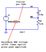
Yes the full EE math with pencil and paper predicts 100V RMS across your snubber resistor and 2 watts of RMS power dissipation.
LTSPICE simulation gives the same result, schematic below.
It's wonderful that your 3W resistor is very efficient at dissipating heat into the surrounding air, without its case becoming uncomfortably hot. Some 3W resistors are not so efficient, and their exterior case does become very very hot.
LTSPICE simulation gives the same result, schematic below.
It's wonderful that your 3W resistor is very efficient at dissipating heat into the surrounding air, without its case becoming uncomfortably hot. Some 3W resistors are not so efficient, and their exterior case does become very very hot.
Attachments
Many thanks Mark for the lightning fast check!
The resistor is a cheap Vishay PR03 series 3W metal film one. I think I'll have better to check its temp once again and probably anyway replace it by a 6W one! That would be a much better and suitable ratio IHMO.
The resistor is a cheap Vishay PR03 series 3W metal film one. I think I'll have better to check its temp once again and probably anyway replace it by a 6W one! That would be a much better and suitable ratio IHMO.
Oops. Didn't see the next page of replies.
I'll take it from Mark's confirming-data-point that you're using a True RMS DVM. 😉
I'll take it from Mark's confirming-data-point that you're using a True RMS DVM. 😉
Many thanks Mark for the lightning fast check!
The resistor is a cheap Vishay PR03 series 3W metal film one. I think I'll have better to check its temp once again and probably anyway replace it by a 6W one! That would be a much better and suitable ratio IHMO.
This resistor (PR03) is fusible and it might blow without you even noticing …
You better find a better resistor for the job.
Metal oxide for example.
As far as I can understand from the resistor's datasheet the fusing features are only related to safety issues. There are no indications about maximum currents. So it seems to be especially suitable for the specific usage.
Still I'd like to install a 6W one later.
Still I'd like to install a 6W one later.
Today I connected my Quasimodo to a 250-0-250V transformer used for the tube section of my DAC. A 600R resistor is required on each leg. What's the expected dissipated power? Could the math behind be published here please?
Thanks!
Thanks!
Here is the math to calculate power dissipated in the snubber resistor. It is typical of a homework problem given to 2nd year EE undergraduates taking their first Circuit Analysis class.
You may decide that the LTSPICE simulation method shown in post #1351, has much to recommend it after all. But either path will lead to your final objective.
Please remember to make the actual resistor in real life, at least 2X and preferably 3X the wattage, compared to the calculated power. This gives a margin of safety for reliability and a long, long service life.
_
- R is the snubber resistance in ohms. In the example of post #1350, R=4700
- C is the series capacitor "Cs" in farads. In the example, C = 1.5E-7 (0.15uF)
- Vin is the secondary RMS voltage in volts. In the example, Vin = 460
- f is the mains frequency in Hertz. In the example, f = 50
You may decide that the LTSPICE simulation method shown in post #1351, has much to recommend it after all. But either path will lead to your final objective.
Please remember to make the actual resistor in real life, at least 2X and preferably 3X the wattage, compared to the calculated power. This gives a margin of safety for reliability and a long, long service life.
_
Attachments
Have Quasimodo V4 through hole version kits for sale in stock. The kit is $36.08 which includes free shipping to the lower states and PayPal fees. The kit is standard BOM. The boards are with ENIG finish. Parts are labeled and packaged in small plastic bags.
Have Quasimodo V4 through hole version kits for sale in stock. The kit is 29USD with free shipping to the lower states. The kit is standard BOM. The boards are with ENIG finish. Parts are labeled and packaged in small plastic bags.
- Home
- Amplifiers
- Power Supplies
- Simple, no-math transformer snubber using Quasimodo test-jig