I’ve never seen a primary-side fuse save output devices from a shorted speaker wire.
I just took apart a 40 year old amp that has never been apart, is cool to see a fuse that you are pretty certain has been there that entire time.
I just took apart a 40 year old amp that has never been apart, is cool to see a fuse that you are pretty certain has been there that entire time.
Using QM v.4 on an Antek 400 VA toroid (AS-4218)
This morning I dragged out my Quasimodo to measure the secondary leakage inductance of a toroidal transformer I might use in an upcoming project: the AnTek AS-4218. It's 2x18VAC at 400 VA, dual primary (115/230), with an electrostatic shield.
Measured secondary inductance was 5.3 microhenries. To get the desired damping factor (zeta = 1.0) in a 2C+1R snubber, with Cx=10nF and Cs=150nF, the correct value of snubbing resistance is 11.5 ohms.
Math check: Zeta = (0.5 / Rs) * sqrt(L / C)
plug in the values {Rs = 11.5} , {L = 5.3E-6} , {C = 1E-8}
Zeta = 1.00 as desired
Although you can use Quasimodo in a no-math procedure if that's what you like, I think it's nice to occasionally be reminded that the math actually works too.
Mark Johnson
Happy longtime QM user here and I recently ran into a new primary secondary configuration that seems to not be explicitly covered in the documentation.
Typically, I have shorted all primary and secondary windings when "ringing" a particular output winding. What happens if in the final deployment of the transformer, I have a unused winding that will be insulated and left as an open circuit?
Do I short this for all measurements, or leave it open, as this effects the measurements and optimal snubbers?
Also, two more "meta" questions:
1.) Does adding snubbers via this method actually lower the presence of 60Hz and its cousin multiple frequency on distortion spectra? I've been meaning to compare this directly but haven't gotten around to doing so.
2.) Is adding the Cs + Rs || Cx per the locations described in the QM equivalent to adding a Cs + Rs || Cx across each diode, as sometimes is seen around here? If not, does this model have a different impact to the spectra noted in Question #1, by changing the switching performance characteristics of the diodes?
Thanks!
If I were using a transformer with an unneeded "extra" winding, I think I'd put a resistor across that winding, value chosen to give ~ 40 milliwatts of power dissipation. Both in the final equipment installation, and in Quasimodo testing. Fear of the unknown I suppose. Sounds like you are installing a resistor too, whose value is VeryMany ohms.
1. Test it and see; I imagine the answer is no since the impedance of Cs is big at 60 Hz
2. The answer to "equivalent??" is available in simulation. The "spectra?" part needs measurements.
1. Test it and see; I imagine the answer is no since the impedance of Cs is big at 60 Hz
2. The answer to "equivalent??" is available in simulation. The "spectra?" part needs measurements.
Finally got to use my Quasimodo;
First I needed to repair it, as I found out it doesn't like 20V supply voltage
Seems the gate driver went faulty, drawing lots of current all of a sudden 🙂
After replacing the gate driver, I settled on a save 10V
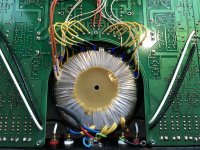
Bit hard, as the transformer is actually in an integrated amplifier, and has 8 separate windings (actually 9, more later), 4 for the power stage, and 4 others for other stuff.
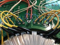
Soldered shorts over all windings, except the one being tested, for which I pulled 1 transformer wire each time from the pcb so the winding is effectively isolated.
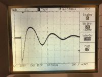
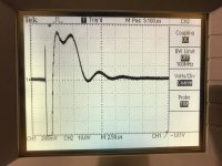
All went fine, except for 1 winding #6, which seemed distorted, but I adjusted it as good as I could.
Results:
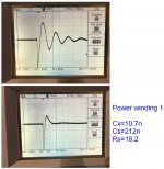
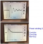
Power Winding#1, 10.7n, 212n, 18.2
Power Winding#2, 9.6n, 214n, 18.2
Power Winding#4, 10.6n, 219n, 18.2
Power Winding#5, 10.6n, 221n, 18.2
Winding #3, 10.7n, 239nF, 68.7
Winding #6, 10.6n, 232n, 56.4 (distorted)
Winding #7, 9.6n, 234n, 20.3
Winding #8, 10.8n, 235n, 20.3
Initially I forgot to short the primary winding, but I actually didn't notice any difference with the primary winding shorted or open.
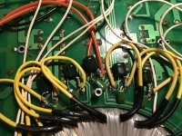
Only when I finished (and soldered in all snubbers), I noticed there was another winding, seemingly unused. Wires isolated in heatshrink, didn't check yet.
I think this may be the reason why I had distorted results on Winding #6.
But now, would I have to start all over ?
For QM testing, instead of the short on other windings, would having the snubbers in place suffice ?
First I needed to repair it, as I found out it doesn't like 20V supply voltage
Seems the gate driver went faulty, drawing lots of current all of a sudden 🙂
After replacing the gate driver, I settled on a save 10V
Bit hard, as the transformer is actually in an integrated amplifier, and has 8 separate windings (actually 9, more later), 4 for the power stage, and 4 others for other stuff.
Soldered shorts over all windings, except the one being tested, for which I pulled 1 transformer wire each time from the pcb so the winding is effectively isolated.
All went fine, except for 1 winding #6, which seemed distorted, but I adjusted it as good as I could.
Results:
Power Winding#1, 10.7n, 212n, 18.2
Power Winding#2, 9.6n, 214n, 18.2
Power Winding#4, 10.6n, 219n, 18.2
Power Winding#5, 10.6n, 221n, 18.2
Winding #3, 10.7n, 239nF, 68.7
Winding #6, 10.6n, 232n, 56.4 (distorted)
Winding #7, 9.6n, 234n, 20.3
Winding #8, 10.8n, 235n, 20.3
Initially I forgot to short the primary winding, but I actually didn't notice any difference with the primary winding shorted or open.
Only when I finished (and soldered in all snubbers), I noticed there was another winding, seemingly unused. Wires isolated in heatshrink, didn't check yet.
I think this may be the reason why I had distorted results on Winding #6.
But now, would I have to start all over ?
For QM testing, instead of the short on other windings, would having the snubbers in place suffice ?
Attachments
-
 All 8 (9 actually) windings.jpg587.3 KB · Views: 809
 -
 All windings shorted.jpg474 KB · Views: 802
 -
 C - Snubbers in place.jpg992.2 KB · Views: 687
 -
 S - Power Winding 1.jpg453.5 KB · Views: 669
 -
 S - Power Winding 2.jpg236.2 KB · Views: 661
 -
 Winding6 (distort).jpg210.1 KB · Views: 269
 -
 Winding6-Snub.jpg1 MB · Views: 287
Having the snubbers in place on all windings except the test winding, and shorting the primary, is imho the better test scenario, as that is what you will have in normal operation.
Obviously as a cross-check, you could also short all those windings again and see what you would have nominally come up with.
I'd anticipate the checking to show little practical change. If there was a substantial practical change then that indicates how much of an expediancy compromise is occurring with the default procedure (shorting all secondary windings other than test winding).
PS. Is that a primary winding wire nearly touching a speaker wire?
Last edited:
Rbroer, you or others could obtain the answers either through simulation or direct measurement. For the latter you'll need a hand held, battery powered oscilloscope which is not connected to the mains or to any "ground" of any equipment. Make sure it's a relatively decent scope with bandwidth >= 20 MHz because you'll need excellent triggering. Unfortunately, low price, low bandwidth scopes usually have terrible triggering. Measure the final equipment's secondary windings in-situ when playing music LOUD, and don't electrocute yourself or destroy the equipment via an accidental slipped probe.
OR you could accept my raw guess obtained via **ctal extraction. My guess is that the effect of the last winding upon all the others, when measuring leakage inductance, is small to negligible. My further guess (controversial! watch the followups!) is that the error this introduces, causes you to build a snubber that is not optimum but which is on the correct side of optimum, so that it provably does much much more good than harm. My raw guess.
OR you could accept my raw guess obtained via **ctal extraction. My guess is that the effect of the last winding upon all the others, when measuring leakage inductance, is small to negligible. My further guess (controversial! watch the followups!) is that the error this introduces, causes you to build a snubber that is not optimum but which is on the correct side of optimum, so that it provably does much much more good than harm. My raw guess.
Last edited:
I am troubleshooting some 100hz buzz in my F6 amp (http://www.diyaudio.com/forums/pass-labs/277850-f6-illustrated-build-guide-109.html#post5369807), which was suggested to arise from rectifier switching noise. I do not own an oscilloscope, but was wondering if it would be possible to use the 100hz (and harmonic) levels as an alternative readout to the oscilloscope ringing? If so, would something like a 100 or 220 nF Cs with a 3.3 nF Cx be an acceptable combination to test with? I also have a 47nF x2 cap i could use as Cs if its better to have the two values closer together?
Sorry, all we do here in this thread is build and use and discuss bellringer test jigs such as Quasimodo. These jigs stimulate transformer ringing so you can easily see it on an oscilloscope. No idea how to get similar results without using either an oscilloscope or a bellringer jig.
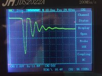
I found that the battery powered "JDS2022A" handheld oscilloscope ($144 at Banggood), gave satisfactory performance when measuring snubbers.
_
I found that the battery powered "JDS2022A" handheld oscilloscope ($144 at Banggood), gave satisfactory performance when measuring snubbers.
_
Attachments
I am troubleshooting some 100hz buzz in my F6 amp (http://www.diyaudio.com/forums/pass-labs/277850-f6-illustrated-build-guide-109.html#post5369807), which was suggested to arise from rectifier switching noise.
If you look above, the hypothesis is that snubbers won’t lower mains frequency related distortion spectra.
You are right, sorry I didn't catch that one, I was acting on advice from another thread and thought to ask. The impedance if the cap at those frequencies is a good point. Would it be possible to damp the low frequencies with an L-R type circuit instead or would it be more sensible to simply add some more filtering to the PSU? Sorry if this is getting off topic...
If you look above, the hypothesis is that snubbers won’t lower mains frequency related distortion spectra.
Calling that a "hypothesis" is too optimistic. If you look above you will see that in fact, it is a "raw guess obtained via rectal extraction"
Fair enough, maybe I will give it a try just for my own curiosity's sake. Does said rectum have any opinion as to whether better soft recovery diodes might ameliate some of the supposed switching noise? I noticed to my horror that I have used Fairchild diode bridges in my build that were among the worst for noise according to your linear audio paper. Specifically the gbpc 3506 (600v version of the 3510's you tested)...
Being unencumbered by electrical engineering expertise that would dissuade me from trying out my own suggestion i went ahead and fitted diode bridges for the amp with 100nF+1K pot and a 3.3nF cap parallel (what i had at hand). Going through the full range of the pot had 0 effect on the FFT. Not solid proof, but i guess that it supports popular opinion, rectally derived or not.
Last edited:
Not really a shock since every single scope photo in the Quasimodo design note and here in this thread, shows the transformer secondary RLC resonant circuit ringing at a frequency somewhere between 50 kHz and 800 kHz.
Not really a shock since every single scope photo in the Quasimodo design note and here in this thread, shows the transformer secondary RLC resonant circuit ringing at a frequency somewhere between 50 kHz and 800 kHz.
This is a compelling argument...
It's an observation. Anybody with eyes could make the same observation, there is no fancy calculus required. But none of the Armchair Theorists did, which is surprising.
"Fair Use"
We need an explanation of what is and is not "Fair Use" of copyrighted material.
Please don't scan and post copyrighted material here.

We need an explanation of what is and is not "Fair Use" of copyrighted material.
I have my diyA "subscription" for this thread, arranged so I get an email notification of new posts here, including the content of the post. The post which moderator 6L6 deleted, included a link to one of those sketchy pdf dumps; a pdf containing a poor-quality scan of Morgan Jones's copyrighted article in Linear Audio magazine. The complete article, all pages. Then moderator 6L6 typed post #1309, which told readers where they could find the article from legitimate sources.
I am not a mind reader but I imagine that "the complete article, all pages" was part of moderator 6L6's decision process.
I am not a mind reader but I imagine that "the complete article, all pages" was part of moderator 6L6's decision process.
- Home
- Amplifiers
- Power Supplies
- Simple, no-math transformer snubber using Quasimodo test-jig