So increasing the 6 large capacitors from 3300uf/35v to 4700uf. (C6, C11, C14, C15, C18, C19).
Still at 35volts?
Thanks!
Yes, you need the cap voltage to be higher than the PSU voltage before the regulators. So, 35V will be fine if you are using a 24V transformer. 24V transformer will give 32V-ish after rectification. A 22V or 24V transformer is what you want, then the regulators will drop the voltage to 24V. Regulators need at least a 2V drop to work depending on which regulator you are using.
I am not sure what you are trying to do but you will need a different transformer than used with the whammy as well if you want to get 24V-ish out of the regulator. But it seems like an easier solution is just to buy a transformer and a cheap lm317/337 regulator kit which are ready available on ebay/amazon/etc. The whammy board has the PSU and amp circuitry on one board...
put 100K bleeder resistor from outer side of output cap to GND
that will prevent cap from floating and you'll not see DC on output anymore
simple as that
that will prevent cap from floating and you'll not see DC on output anymore
simple as that
I am sorry to ask such a basic question, but I don’t want to start my BA-3 build by killing a transformer. I am using the 50va Antek AS-0520 with dual 20v secondaries. I wanted to do an initial build with one of these simple, ubiquitous LM317/LM337 boards. Should I connect the the two secondaries in parallel to the two AC input pads? Leaving the AC GND pad empty? Want to get this right..the first time. Thanks all — I’ve enjoyed reading this thread as I prepare my build. I will be consulting the archive often.

To me it looks like a PSU board that gives to a symmetrical DC output....like -24V, Gnd, +24V. Then you should not parallel the two AC secondaries but serial them. Then the center tap is the Gnd and you have a -20VAC and a +20VAC.....but someone that knows the PSU board should comment…….because I can't see where the rectifier diodes are…..I assume it is "onboard"......I can see some diodes but not 100% sure they are the rectifiers……..or you should rectify before the board.....but then it is more like an unregulated DC in.....than an AC in as written on the PCB.
I am sorry to ask such a basic question, but I don’t want to start my BA-3 build by killing a transformer. I am using the 50va Antek AS-0520 with dual 20v secondaries. I wanted to do an initial build with one of these simple, ubiquitous LM317/LM337 boards. Should I connect the the two secondaries in parallel to the two AC input pads? Leaving the AC GND pad empty? Want to get this right..the first time. Thanks all — I’ve enjoyed reading this thread as I prepare my build. I will be consulting the archive often.
An externally hosted image should be here but it was not working when we last tested it.
Hi jphabc54
There are no "basic" questions on your first attempt. The circuit board you posted appears to have 4 diodes forming 2 full wave rectifiers, one generating the DC+ and one the DC-. You need a center tapped transformer to provide the AC to a full wave rectifier. If you want to see what I'm talking about, go to the following link and have a look at the second diagram on the page. Basically, your regulator board has two of these full wave rectifier circuits, one generating the DC+ and the other the DC-.
https://www.electronics-tutorials.ws/diode/diode_6.html
Your transformer has two secondary outputs. The Antek web page for the AS-0520 shows that each secondary has a green and a blue wire. If you join the green wire from one secondary to the blue wire from the other secondary, that makes your center tap. That should be connected to the ground on the AC input side. The other green wire is connected to one AC input pad and the other blue wire to the second AC input pad. The ground on the DC side of the board should be connected to the chassis ground and amplifier ground.
If you look at the first page of this thread, there are photos of a very similar regulator board being used. It's difficult to see the input wiring, but you can just make out that there is a green and a blue transformer secondary wire connected to the two AC inputs and a green and blue wire both connected together to the single ground input. The output wiring is far clearer and should provide guidance on connecting the power board ground to the amplifier and also connecting the power board ground to the chassis earth (the black wire in the last 2 photos on the page).
Good Luck!
Thank you so much vcec for the incredibly helpful response! I noticed the PS-12 that 6L6 used in the build guide was also designed for a center tap, but I did not have any confidence I was interpreting correctly how the dual secondaries were connected to a center tap PSU board.Hi jphabc54
There are no "basic" questions on your first attempt. The circuit board you posted appears to have 4 diodes forming 2 full wave rectifiers, one generating the DC+ and one the DC-. You need a center tapped transformer to provide the AC to a full wave rectifier. If you want to see what I'm talking about, go to the following link and have a look at the second diagram on the page. Basically, your regulator board has two of these full wave rectifier circuits, one generating the DC+ and the other the DC-.
https://www.electronics-tutorials.ws/diode/diode_6.html
Your transformer has two secondary outputs. The Antek web page for the AS-0520 shows that each secondary has a green and a blue wire. If you join the green wire from one secondary to the blue wire from the other secondary, that makes your center tap. That should be connected to the ground on the AC input side. The other green wire is connected to one AC input pad and the other blue wire to the second AC input pad. The ground on the DC side of the board should be connected to the chassis ground and amplifier ground.
If you look at the first page of this thread, there are photos of a very similar regulator board being used. It's difficult to see the input wiring, but you can just make out that there is a green and a blue transformer secondary wire connected to the two AC inputs and a green and blue wire both connected together to the single ground input. The output wiring is far clearer and should provide guidance on connecting the power board ground to the amplifier and also connecting the power board ground to the chassis earth (the black wire in the last 2 photos on the page).
Good Luck!
This is great--now I can proceed on my PSU with confidence!
One more question for the group. I am going to build a BA-3 and an F5 over the next several months. For these projects I have two matched pairs of the Toshiba 2SJ74-BL/2SK170-BL (7.42 and 7.45 IDSS respectively) and two matched pairs of the Linear Systems grade B LSJ74/LSK170 from the DIY Audio store (unknown IDSS).
I'm planning to build the BA-3 first. Given the choice, would the BA-3 be a better served by NOS Toshibas or new LS's? Or does it not really matter?
Thanks!
I'm planning to build the BA-3 first. Given the choice, would the BA-3 be a better served by NOS Toshibas or new LS's? Or does it not really matter?
Thanks!
Are you building both as power amps? Or will one be a pre and the other power?
Anyway, the Toshiba and Linear are interchangeable in terms of sound quality. Both are wonderful.
Anyway, the Toshiba and Linear are interchangeable in terms of sound quality. Both are wonderful.
Are you building both as power amps? Or will one be a pre and the other power?
Anyway, the Toshiba and Linear are interchangeable in terms of sound quality. Both are wonderful.
Thanks! I'm building the BA-3 and the F-5 as a preamp/power amp combo for a second system.
Build a BA-3 complimentary amp and toss a 25K pot in front of it (and maybe some selection) to be an integrated amp. 🙂 🙂 🙂

Suitable for iron pre?
Tamura MG-21 Input audio Transformer 1:1 impedance matching / FREE SHIPPING / | eBay
Tamura MG-21 Input audio Transformer 1:1 impedance matching / FREE SHIPPING / | eBay
Attachments
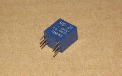

it look damn small ?!?
anyway - considering that Iron Pre is made to accommodate 3 types of xformer - Edcor , Jensen and Cinemag ..... you have a choice ...... using any other is welcomed , but impossible to comment without actual experience
Oh man -- too, too many choices!
The BA-3 as a stand-alone pre looked like a fun, cheap, and easy way to reuse a 3U Pesante chassis currently collecting dust (and would look and sound sharp stacked with an F-5 housed in a 4U dissipante!).
And I already have the boards, JFETs, PSU's, and transformers for both!
The BA-3 as a stand-alone pre looked like a fun, cheap, and easy way to reuse a 3U Pesante chassis currently collecting dust (and would look and sound sharp stacked with an F-5 housed in a 4U dissipante!).
And I already have the boards, JFETs, PSU's, and transformers for both!
Iron Pre - not sure exactly what this is but if I were to guess a transformer to make the BA-3 preamp balanced at the input? But since this was not in context maybe it is about another use? "Iron pre" in subject line gave no results on forum search.
Question #2 which has my interest from this thread. The Sparkfun THAT 1646 reference earlier. I'm trying to recall the scenario - but how much voltage or current on the input side is this meant to work with? (sparkfun site has example on CD player) I was wondering about after a BA-3 pre, but also have it in mind for output on a tube pre
Question #2 which has my interest from this thread. The Sparkfun THAT 1646 reference earlier. I'm trying to recall the scenario - but how much voltage or current on the input side is this meant to work with? (sparkfun site has example on CD player) I was wondering about after a BA-3 pre, but also have it in mind for output on a tube pre
Last edited:
- Home
- Amplifiers
- Pass Labs
- The BA-3 as preamp build guide