I can’t wait... wanted to see how the back panel looks with mounted hardware.
Man those look great!
Bought a Yamaha wxc-50 streamer/dac/pre. Could be ideal. Have to finish my ACA first before I can report my findings...I was referring to the cheap VC upgrade that is offered as an add-on. It doesn't sound different, but tracks better between channels at low volumes.
Here is why I like the Transcendent kit:
- is extremely quiet and sounds very good.
- has gain.
- is not too expensive (relatively speaking), and is accessible to people like me who do not have much understanding of circuit design.
- doesn't poop out into low impedance amplifiers like some of the other gear I've tried.
I am generally interested in trying new projects, especially during the long winters where I live. I've built the B1 buffer, which sounds nice but does not have gain and thus is not a good match for the ACA and my speakers. Do you have recommendations that are more in line with ACA spirit that can be built reasonably easily by people like me (who don't have much electronic design understanding)? I would be particularly interested in a balanced design that would play well with the balanced bridged ACA.
Thanks
Jaaptina, I wish you good luck. From the specs, the output of the Yamaha pushes 2V with an impedance of 470 Ohms. Numbers don't look that promising for the match up. The bare minimum of impedance ratio between output and input should be 10, but you have heard here recommendations of 100! You have 20:1. Voltage is also on the lower realm.
There's an option to add +6dB of gain, but that brings the THD to 0.9%, so not sure that is something you are OK with.
It seems like the Yamaha is built to match with much 'beefier' amps.
I may be completely wrong, or your speakers are very efficient and this won't be much of a problem.
Best regards,
Rafa.
Last edited:
So parallel not such a good idea even if my preamp has two single ended and two balanced outputs? Each channel driven by an independent single ended output from the pre but it won’t matter if the ACA speaker level outputs are paralleled right?
Anyway I’m keeping them balanced bridged. The ML Motion 40 are working fine. While I couldn’t find an impedance graph there was a review in Sound and Vision where they state:
Anyway I’m keeping them balanced bridged. The ML Motion 40 are working fine. While I couldn’t find an impedance graph there was a review in Sound and Vision where they state:
Impedance reaches a minimum of 3.48 ohms at 111 Hz and a phase angle of –44.04 degrees at 69 Hz.
Read more at MartinLogan Motion 40 Speaker System HT Labs Measures | Sound & Vision
Last edited:
Thanks Rafa! I did not know this. If I get disappointed then I know now what to change.Jaaptina, I wish you good luck. From the specs, the output of the Yamaha pushes 2V with an impedance of 470 Ohms. Numbers don't look that promising for the match up. The bare minimum of impedance ratio between output and input should be 10, but you have heard here recommendations of 100! You have 20:1. Voltage is also on the lower realm.
There's an option to add +6dB of gain, but that brings the THD to 0.9%, so not sure that is something you are OK with.
It seems like the Yamaha is built to match with much 'beefier' amps.
I may be completely wrong, or your speakers are very efficient and this won't be much of a problem.
Best regards,
Rafa.
Any recommendations for a better matching dac/pre?
Last edited:
Thanks Rafa! I did not know this. If I get disappointed then I know now what to change.
Any recommendations for a better matching dac/pre?
LSK pre - BAF 2013
Roland - Super UA | USB Audio Interface
LSK Pre is , without buffer , having highish Rout
It does.
I wanted to point to an exceptional thread that contains LSK, LSK with a buffer, JFET, BJT designs (non-unobtainium transistors !!!!!!!!! that we can actually buy for 5 bucks or so, instead of 100 😡😡😡 ), simple LSK with LatFET' output stage, PCB design(s)... truly educational and informative thread by our fellow countryman Juma
We had a little demo session, regular bunch, kids as the ultimate unbiased referees. 2A3, 300B, 6S33S, push-pull MOSFET amps and... ACA's
Kids liked ACA's best. Nothing special at its input, just a 33ohm I/V resistor and the current straight from the DAC chip.
The rest of us were biased... but we also liked ACA's the best😱😱
Kids liked ACA's best. Nothing special at its input, just a 33ohm I/V resistor and the current straight from the DAC chip.
The rest of us were biased... but we also liked ACA's the best😱😱
name of the game is ....... fun
best when unspoiled with prejudices and pre-expectations
it can be very revealing
🙂
best when unspoiled with prejudices and pre-expectations
it can be very revealing
🙂
We had a little demo session, regular bunch, kids as the ultimate unbiased referees. 2A3, 300B, 6S33S, push-pull MOSFET amps and... ACA's
Kids liked ACA's best. Nothing special at its input, just a 33ohm I/V resistor and the current straight from the DAC chip.
The rest of us were biased... but we also liked ACA's the best😱😱
Yes... but biased to 10 volts or 12? 🙂
Yes... but biased to 10 volts or 12? 🙂
My setup uses 2 ACA(s) in the balanced input configuration. They each drive a heil AMT. (Active crossover]
I have biased at 10 on one amp 12 on the other. Just waiting on another 24v supply to even that up. Sonically there may be a difference but - darned if I can hear it.
Either way - what a fantastic sounding amp!
Hahahahaha... this was a very elegant joke! Just to write that it wasn't lost to all of us confused with technical data! 🙂Yes... but biased to 10 volts or 12? 🙂
Rafa.
I feel overwhelmed to be posting in this mega-thread, but I'm interested in using an ACA as a very small amp for desktop speakers. (I know there are many integrated circuit ways to do this, but I want to try my hand at scratch-building in class A.) I am looking for around 1W of output.
Someone mentioned the FAOW, but it has less efficiency than I might want for under my desk (in my SPICE model it draws 27W from the power supply and delivers under 0.5W to the speaker). Someone else mentioned the ACA as a possiblity. I wonder if it is possible to use an ACA with a lower supply voltage (12V?) and get the same clean output at 1W?
I built a SPICE model of the ACA with R15 and I see 3.7W out from a 1Vpk input while drawing 29W from the power supply. (Does that seem correct behavior for a model of the ACA? THD around 0.3% at that input level?)
I tried just turning the supply voltage down to 12V, but I'm sure that I'm getting the biasing wrong because the same 1Vpk input delivers 2.7W into the load, but with THD of almost 7%. I think that I need to adjust R10 to change the DC bias point of the output FET (SPICE says 7.75V DC at the junction of R3 and R4), but I'm not sure how to accomplish that, nor what I should be aiming for. Do I want the DC voltage at that point to be a certain value, or do I want the quiescent current drawn from the power supply to be a certain value? In my model right now, with a 12V supply, the quiescent current is .33A. Is that just too small?
Thanks in advance for any suggestions you can offer and my apologies for asking such basic questions here.
-Neil N0FN
leave rail at 19V , just work on lesser Iq
dissipation and power goes down and that's it
with rail going down , bad capacitances of mosfets are getting nasty
dissipation and power goes down and that's it
with rail going down , bad capacitances of mosfets are getting nasty
12V is not going to work; class a operating range would be way to small + (with the ACA biasing) -> the transistors can't go into conducting state. However, you could use ACA as a hands/fingers warmer during the winter period, especially if placed next to a keyboard.
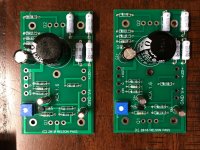
Started my ACA build last night and made some pretty good progress. I noticed the 1.6 boards have (5) holes for mounting. I haven't looked at my heatsinks yet but from 6L6's photos it looks like they have (5) corresponding holes as well. Has anyone used the (4) outer holes to mount their boards? Any reason not to? I guess I just like the idea of the board being mounted at (4) points vs. (1) + the mosfets.
Attachments
Started my ACA build last night and made some pretty good progress. I noticed the 1.6 boards have (5) holes for mounting. I haven't looked at my heatsinks yet but from 6L6's photos it looks like they have (5) corresponding holes as well. Has anyone used the (4) outer holes to mount their boards? Any reason not to? I guess I just like the idea of the board being mounted at (4) points vs. (1) + the mosfets.
Looking at the v1.5 build guide:
Amp Camp Amp V1.5 Build Guide - diyAudio Guides
it appears to me that versions prior to v1.6 came with only one additional mounting hole. From a "makes good sense to me" perspective, I'd agree with where I think you're going. I can't see any reason not to secure the PCB at all its mounting points if that lines up with the mounting hole pattern in the heatsink. I'd be interested to read if there's a sneaky reason not to use them.
Thanks for the tip off.
Last edited:
Not exactly 🙂
The idea is to measure the applied AC signal and the AC output level using a DVM to try and see why one of your channels is quieter than the other.
First disconnect the speaker. Now connect just one input socket to your player/preamp because we are testing each channel separately.
1/ Set the meter to AC voltage.
2/ Connect the black lead of the meter to the Red speaker socket (which is ground on the ACA)
3/ Connect the red lead of the meter to the Black speaker socket.
4/ Play the tone and adjust the volume to give a reasonable output voltage on the channel under test. The ACA should be able to easily reach 6 volts rms so aim for that.
(Absolute value is unimportant because we are only comparing readings and also seeing if the gain works out correctly)
Write the result down.
5/ Now transfer the red meter lead to the 'input' side of R11. This is the end that goes to the input wiring and sockets.
6/ Without altering the volume write down the reading you see.
Those two results give you an output voltage and corresponding input voltage. From those two results we can confirm if the board is working correctly.
8/ Without altering any settings now swap the input to the other channel and repeat the test. You should be seeing similar readings of output voltage and input voltage on R11.
Lets see where yours falls down on this.
Hi Mooly,
Did the above measurements: On one channel with both leads into speaker posts: .844v and with red lead to input of R11 .244v This channel has sound.
On the other board, both showed .001V. This board has sound on the speaker because at power off there is loud pop.
Please take note, this used to be the good amp which I replaced in service with the now fixed amp.
Did some re-soldering on it and when I re-installed it, sound is gone, but both speakers have loud sound when amp is switched off.
Is .001v no voltage at all? And are the other voltages correct?
How do we fixed this?
Thanks.
Started my ACA build last night and made some pretty good progress. I noticed the 1.6 boards have (5) holes for mounting. I haven't looked at my heatsinks yet but from 6L6's photos it looks like they have (5) corresponding holes as well. Has anyone used the (4) outer holes to mount their boards? Any reason not to? I guess I just like the idea of the board being mounted at (4) points vs. (1) + the mosfets.
It's looking good; soldering job in particular
You can use a minimum of one I suppose - the middle one, to help you with correctly positioning the PCB away from the heatsink. It won't harm to use more. The whole PCB with that miniature 3300uF cap, is very light, I wouldn't worry about its weight even if you use only the middle distancer.
..just realized... you position all the resistors in one direction... looks nice!
Last edited:
- Home
- Amplifiers
- Pass Labs
- Amp Camp Amp - ACA