Hi Mooly,
Did the above measurements: On one channel with both leads into speaker posts: .844v and with red lead to input of R11 .244v This channel has sound.
On the other board, both showed .001V. This board has sound on the speaker because at power off there is loud pop.
Please take note, this used to be the good amp which I replaced in service with the now fixed amp.
Did some re-soldering on it and when I re-installed it, sound is gone, but both speakers have loud sound when amp is switched off.
Is .001v no voltage at all? And are the other voltages correct?
How do we fixed this?
Thanks.
Just an option and a friendly suggestion.... it seems that you are struggling a bit even under an expert guidance; see if there are any of your fellow countrymen (DIY-ers) living close by... maybe they can provide a helping hand.
Started my ACA build last night and made some pretty good progress. I noticed the 1.6 boards have (5) holes for mounting. I haven't looked at my heatsinks yet but from 6L6's photos it looks like they have (5) corresponding holes as well. Has anyone used the (4) outer holes to mount their boards? Any reason not to? I guess I just like the idea of the board being mounted at (4) points vs. (1) + the mosfets.
In V. 1.5 the center hole has an important function. It creates electrical contact from GND to chassis (heatsink). So this connection should be the only point where the ACA GND has chassis connection so no ground loops are created. At least that is my understanding of how it works……. 🙂 I have not seen it explained officially…..but I think the person who made the PCB layout has thought about it 🙂
If you look at the backside of the v. 1.6 PCB you can see if the center hole is electrical isolated or it has a connection to ACA GND?
How to get the result of 8W output of ACA amp.of V1.5?
Please tell me how to calculate it. Thanks in advance!
Please tell me how to calculate it. Thanks in advance!
In V. 1.5 the center hole has an important function. It creates electrical contact from GND to chassis (heatsink). So this connection should be the only point where the ACA GND has chassis connection so no ground loops are created. At least that is my understanding of how it works……. 🙂 I have not seen it explained officially…..but I think the person who made the PCB layout has thought about it 🙂
If you look at the backside of the v. 1.6 PCB you can see if the center hole is electrical isolated or it has a connection to ACA GND?
The centre eyelet has a provision to establish DC contact with the heatsink, if a metal distancer is used. There's another one, the corner one that does the same. I don't think it makes much of a difference if both eyelets make a DC conntact with the heatsink. There's a third connection point - at the 24DC socket, at the back of the amplifier. I suppose that would be a chassis ground point... so the distancers could be nylon ones, to provide isolation?
I made two connection points, at those two PCB eyelets... but I do not have a 24DC socket at the back - I moved the SMPS inside the ACA🙂. My ACA's are completely quiet.
Hi Mooly,
Did the above measurements: On one channel with both leads into speaker posts: .844v and with red lead to input of R11 .244v This channel has sound.
On the other board, both showed .001V. This board has sound on the speaker because at power off there is loud pop.
Please take note, this used to be the good amp which I replaced in service with the now fixed amp.
Did some re-soldering on it and when I re-installed it, sound is gone, but both speakers have loud sound when amp is switched off.
Is .001v no voltage at all? And are the other voltages correct?
How do we fixed this?
Thanks.
Hi,
Your posts are a bit spread out now. Can you restate the problem please?
1 amp working and 1 faulty. Both not working - which?
The 'pop' is just C1 (the big cap) charging / discharging - it proves very little.
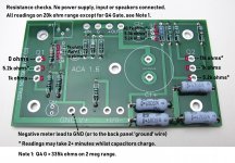
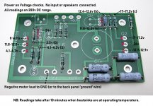
I posted a couple of resistance and voltage check pictures a while ago, #5600 & #5650, maybe give us some of the readings you get off your board(s) to compare?
Extreme_Boky is correct, if you have someone close by who could help.
Attachments
Last edited:
The centre eyelet has a provision to establish DC contact with the heatsink, if a metal distancer is used. There's another one, the corner one that does the same. I don't think it makes much of a difference if both eyelets make a DC conntact with the heatsink. There's a third connection point - at the 24DC socket, at the back of the amplifier. I suppose that would be a chassis ground point... so the distancers could be nylon ones, to provide isolation?
I made two connection points, at those two PCB eyelets... but I do not have a 24DC socket at the back - I moved the SMPS inside the ACA🙂. My ACA's are completely quiet.
I had the impression that all connectors on the back panel was electrical isolated from the chassis (also the power connector but I don't use that either). I also only have one ACA in each stereo chassis and the center hole of ACA PCB is the only point where there is electrical contact to chassis. My ACAs are also "dead silent". What is impressive is that the "sshhhhyyy" in the tweeter.....which will always be there…..to some degree....I have to concentrate a lot to be able to hear it with ear as close as it is possible to the tweeter.
I was also able to get my 300b tube amp that silent…...
Hi Mooly,
Did the above measurements: On one channel with both leads into speaker posts: .844v and with red lead to input of R11 .244v This channel has sound.
On the other board, both showed .001V. This board has sound on the speaker because at power off there is loud pop.
Please take note, this used to be the good amp which I replaced in service with the now fixed amp.
Did some re-soldering on it and when I re-installed it, sound is gone, but both speakers have loud sound when amp is switched off.
Is .001v no voltage at all? And are the other voltages correct?
How do we fixed this?
Thanks.
The readings show that the good channel is in fact operating correctly. An input voltage of 0.244 volts would be expected to give approximately 0.844 volts output. So all good there.
0.001 volts on both output and input of the other board show that there is no applied input signal present.
Causes can only be either a lack of continuity from R11 to the input socket (including continuity through the switch), or a short circuit on the input wiring that is removing the audio.
If you compare with the good amp you will probably find the good one has direct continuity from R11 to the RCA input socket, and the bad one has either no continuity, or there is a short circuit from R11 or the socket to ground.
I posted a couple of resistance and voltage check pictures a while ago, #5600 & #5650, maybe give us some of the readings you get off your board(s) to compare?
Thanks for the measurements. Should be very helpful.
Not strictly speaking a build question, but is the more liquid sound I'm enjoying a facet of Class A, and does it (as the wizard has hinted) include slight distortion?
I've never been a great one for measurements and stats, but suspect that in theory my trusty Meridian G57 has better figures - but for pure pleasure there simply is no contest.
I've never been a great one for measurements and stats, but suspect that in theory my trusty Meridian G57 has better figures - but for pure pleasure there simply is no contest.
It is always difficult with these figures as with class A/B the figures can be very good at close to full output power but may not be very good at e.g. 50-100 mW output which can give a "harsh" sound compared to class A......and especially single ended (which is the purest class A you can get) ….they are masters in good sound down into the mW area….which is very important when instruments fades out etc.....it gives a very good feeling for the room the recording was made in. That is my conclusion after shifting from class A/B to single ended class A (both tubes and FETs based).
That's my experience as well.
In fact...I no longer own any class A/B (push/pull) amps.
I do use class D for my subs though.
In fact...I no longer own any class A/B (push/pull) amps.
I do use class D for my subs though.
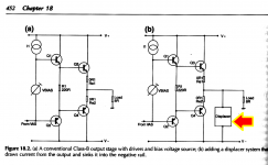
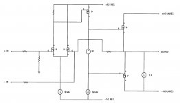
Try Douglas Self's "XD" approach. It does to power amplifiers, today, the exact same thing that nosebleed audiophile tweekers did to opamps 30 years ago:
Self recommends Isink = 1.0 ampere for power amplifiers. Running the EE algebra through a calculator, that means the power amp operates single ended Class-A at all power levels less than or equal to 4 watts (8 ohm load); or single ended Class-A at all power levels less than or equal to 2 watts (4 ohm load). Of course this increases DC power consumption; Self then discusses a couple of pirouettes and backflips that achieve the same goal at considerably less cost in power.
Here's a diagram from Self's textbook, 6th edition:
_
Take a Class-B or "mildly" Class-AB power amplifier. Connect a current sink between the output pin and the negative power supply rail. Voila! It's now Class-A (in fact: single ended Class-A !!) for small swings. How small? Any swing whose output current is less than the value of the current sink.
Self recommends Isink = 1.0 ampere for power amplifiers. Running the EE algebra through a calculator, that means the power amp operates single ended Class-A at all power levels less than or equal to 4 watts (8 ohm load); or single ended Class-A at all power levels less than or equal to 2 watts (4 ohm load). Of course this increases DC power consumption; Self then discusses a couple of pirouettes and backflips that achieve the same goal at considerably less cost in power.
Here's a diagram from Self's textbook, 6th edition:
_
Attachments
How to get the result of 8W output of ACA amp.of V1.5?
Please tell me how to calculate it. Thanks in advance!
With a constant 8 ohm impedance load (an 8 ohms resistor):
8W RMS equals 8V RMS. P=V^2/R; where P=8 watts; R=8 ohms and you solve for V.
Gain of the ACA 1.6 is around 11 dB. Some of the ACA variants have been 14 dB gain, but you can use the same calculations below to calculate the input sensitivity.
Gain = 20 log (V/V); 11 = 20 log (8/X); solve for X; X = 2.25V RMS.
So...for 8V RMS AC you have to input 2.25V RMS AC. 2.25V RMS would be the max input sensitivity with a gain setting of 11dB.
8V RMS will give you about 3% THD in this design which is about the max power. If you input more than 2.25V to 2.5V, you will start to see clipping occuring, you need oscilloscopes, spectrum analyzers, etc...a regular multimeter will not tell you anything regarding this.
Of course if you crank up the volume and at some point it sounds bad, you might be clipping so that’s another way to tell! 😉
Best,
Anand.
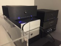
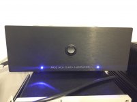
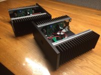
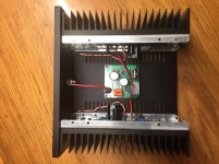
My two ACA’s are playing after a days work. They are truly value for money.
Of course they have to break in a little longer.
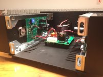
Internally I used silver wiring. Also mounted a CM from Allo eating 0,3V away. I solderd the wires directly to the CM. It’s mounted after the switch.
At this moment they already sound marvelous. Class A a little tube like. They remind me of my Audio Note Conquest amps. Same power approx. same signature. Promising!
tbc!
Thanks Mr Pass! Thanks DIY audio team! Thanks diy members!
Of course they have to break in a little longer.
Internally I used silver wiring. Also mounted a CM from Allo eating 0,3V away. I solderd the wires directly to the CM. It’s mounted after the switch.
At this moment they already sound marvelous. Class A a little tube like. They remind me of my Audio Note Conquest amps. Same power approx. same signature. Promising!
tbc!
Thanks Mr Pass! Thanks DIY audio team! Thanks diy members!
Attachments
-
 40CB46CA-F4DE-4F21-AF32-08BD6C754F72.jpg493.3 KB · Views: 498
 -
 5DB60593-8ADB-4D07-B77D-8CC350A04020.jpg478.8 KB · Views: 482
 -
 84F54914-A00A-44CE-8944-2027E8CBD96D.jpg691.8 KB · Views: 251
 -
 A14AE73E-9178-4FCB-AB83-93292BC655D5.jpg623.9 KB · Views: 481
 -
 D9B92FDB-74C1-40AB-8251-4BDDD648E350.jpg638.8 KB · Views: 239
 -
 66C743BB-E807-4A37-80FB-C6CA93F4BE5C.jpg612.9 KB · Views: 234
 -
 DB2AA460-2EFD-4687-B5AB-8FC4964C8D77.jpg459.3 KB · Views: 1,075
 -
 0761B8B0-AAC6-4FD9-AE8D-36DD1C6A2FAB.jpg596.2 KB · Views: 235
 -
 3FD755F5-6264-4E5B-BEB1-3995CF5B6178.jpg567.4 KB · Views: 237
 -
 E755065C-EBDB-4228-8D9E-8095375DD200.jpg739.9 KB · Views: 235
Nice one JeffreyD.
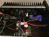
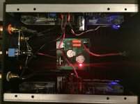
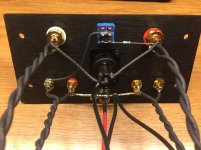
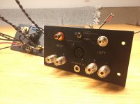
With the CM, how is the input ground dealt with? There's not enough light in the shot for me to make out that detail. Or are you just working off the single connection back to the bus that's wired up to the back plate DC jack?
Any thoughts on the possibility of making the CAD files of the back plate engraving available?
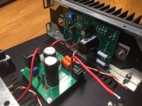
Photo's 3 and 4 show a black wire from the CM ground (0VDC) near the 4 way Molex connector back to the OV bus at the input connector to the amp.
Good idea to put the CM in the amp chassis, close to the ACA V1.6 PCB's.
That is what I will be doing, with an external regulated 24VDC supply feeding the ACA with separate +24VDC supplies for each channel and 2 off CM pcb's - one for each ACA channel.
Good idea to put the CM in the amp chassis, close to the ACA V1.6 PCB's.
That is what I will be doing, with an external regulated 24VDC supply feeding the ACA with separate +24VDC supplies for each channel and 2 off CM pcb's - one for each ACA channel.
Nice one JeffreyD.
With the CM, how is the input ground dealt with? There's not enough light in the shot for me to make out that detail. Or are you just working off the single connection back to the bus that's wired up to the back plate DC jack?
Any thoughts on the possibility of making the CAD files of the back plate engraving available?
... ohh, forgot to mention, it will be really great to hear from you how the CM performs under load once you've got everything settled in, especially in light of this comment:
Using thin wires, multiple connections, crimps, and capacitance multipliers' PCB on various boards with more thin wires... ain't gonna cut it...
Yeah, that's what my eyes tell me but I was just wanting to check I hadn't missed anything.Photo's 3 and 4 show a black wire from the CM ground (0VDC) near the 4 way Molex connector back to the OV bus at the input connector to the amp.

Last edited:
ACA 1.6 Fun
Hi,
Wondering about a couple of things. I ordered the ACA without the front power switch.
1. Cosmetically, I didn’t want it in the front. Can you still install it on the back somehow? Drill a hole?
2. I want to run my ACA’s as a pair of balanced monoblocks (I bought two kits). From the build guide, it looks like you can flip the switch to run them stereo or monoblocks. Does flipping the switch make them from stereo to mono - single ended AND balanced - depending on how you hook them up (use RCA cables for single ended, XLR for balanced)?
Thanks in advance for any assistance you can provide.
Jim.
- Home
- Amplifiers
- Pass Labs
- Amp Camp Amp - ACA