Pot and X121 pinout?
Could someone please help me with the wiring of the pot? I want to use an attenuator not soldered onto the pcb, but I am unsure where the in, out and gnd must go on the pcb. Googling the pinout of the proposed Alps RK09L did not give meaningful info.
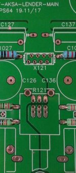
I think I have it figured, but could you also please confirm the pinout of X121?
Could someone please help me with the wiring of the pot? I want to use an attenuator not soldered onto the pcb, but I am unsure where the in, out and gnd must go on the pcb. Googling the pinout of the proposed Alps RK09L did not give meaningful info.
I think I have it figured, but could you also please confirm the pinout of X121?
Attachments
I believe you can get a remote controlled motorized Alps pot kit similar to this.
MV04 Remote Control & Input Potentiometer 9-12V AC Quadruple ALPS Motorized 6256299526620 | eBay
Could someone please help me with the wiring of the pot? I want to use an attenuator not soldered onto the pcb, but I am unsure where the in, out and gnd must go on the pcb. Googling the pinout of the proposed Alps RK09L did not give meaningful info.
I think I have it figured, but could you also please confirm the pinout of X121?
Rows left to right from above:
GND/Left-out/Left-in
GND/Right-out/Right-in
Out is connected to wiper.
Rows left to right from above:
GND/Left-out/Left-in
GND/Right-out/Right-in
Out is connected to wiper.
And what is the fourth hole for?
.
You mean extra row? That’s to accommodate two different pin row spacings. Third row on bottom is same as second row. Two big holes for metal support bracket.
You mean extra row? That’s to accommodate two different pin row spacings. Third row on bottom is same as second row. Two big holes for metal support bracket.
Sorry, I was looking at wrong connector (X121). 🙄 duh
.
X121 is top row all GND,
bottom row: Left Out/Left In/Right In/Right Out.
Thanks X. Not building yet, but I'm planning to connect two pots via shielded cable so that I can have balance adjustment - like on the B1. Channel balance is important to me.
.
Thank you X - to the rescue as always! I see that it corresponds to the Alps RK27 pins which I have hot wired before, but somehow I doubted when I looked at this pcb. At least my feeling about X121 was correct. My confidence is now restored. 😱Rows left to right from above:
GND/Left-out/Left-in
GND/Right-out/Right-in
Out is connected to wiper.
I don't want to make any mistakes here - these boards are sooo nice. Had to de-solder the incorrect diode on the motherboard and that was painful enough.
GASCo, it looks about right, but check for the following changes on the DB TH BOM. It is a bit difficult for me since you have not included the pcb Part numbers in the Mouser BOM.
R10 – Keep it at 10k (carbon film recommended), see Post #608.
R11 – Increase this to lower the gain, see Post #602.
R11 = 1k for MoFo, F4
R11 = 2k2 for ACA, M2
Good, I see that you have made the following corrections to the BOM for the MB:
R141 – 10k, not 220R
V141 – 1N400X rectifier diode, not zener or breakdown
Great, looks like you are good to go!
Thanks Twocents!
I'm ready to buy the components. I noticed there is no R10 in the BOM. I was missing it. I now updated the BOM with the Tag numbers for each component.
I ended up buying a big pack of varied resistors so I dropped the trimpot for 15.
I believe I'm ready to go. It just sucks Mouser charges so much for shipping. I want to be completely sure I'm not missing a $0.40 part and having to pay $7 for shipping again.
These should be final:
MB: Mouser Electronics
DBTH: Mouser Electronics Resistor 2.2K added for gain for ACA. The tag numbers don't match because they're also being used on the MB
I see that you mounted your pot remotely. Did you just soldered the wires into the MB or used some kind of connector?
Not sure what you mean by this? All the parts are numbered uniquely and can be matched to a particular board. If all else fails - consult the schematics!The tag numbers don't match because they're also being used on the MB
The R122, R132 tags in DBTH should probably be R11 (for 2.2K).These should be final:
MB: Mouser Electronics
DBTH: Mouser Electronics Resistor 2.2K added for gain for ACA.
Everything else looks fine, but I did not check your hardware. I don’t see any channel selector (S101) or heatsinks (for V142, Q4, Q5)
I see that you mounted your pot remotely. Did you just soldered the wires into the MB or used some kind of connector?
Yes, that is the plan to mount the pot remotely - still a work in progress. I will probably also just solder the wires directly onto the pcb like Vunce and drpro (Post #494).
Tag numbers as in R122, R132. The numbers that are associated to that part on my Mouser account, just because that part is also part of the MB.
Thanks for your answers!
Is there an easy way to have a balanced output added? Newbie question but if it is stupid I'll figure out when I have no answers!
Thanks for your answers!
Is there an easy way to have a balanced output added? Newbie question but if it is stupid I'll figure out when I have no answers!
Regarding balanced output: no “easy” way except to add a pricey balun transformer and that adds its own sound signature as they are not acoustically transparent.
There are opamps that take single ended to balanced out by THAT Corp. But you are now putting Class AB opamp at the end of your nice SE Class A Preamp!
Hugh has a very nice single ended to balanced drive converter that is SE Class A but it is not for DIYA.
Alternatively, if you have a balanced source and you want balanced outputs, build two preamps and use a 4-gang pot. That would be “simple” conceptually.
Gotcha.
I'll live without it, then. I don't have balanced sources. I just thought that I could use the extra 5WPC the ACA gives when bridged w/ balanced inputs.
I received the board last Tuesday. Thanks! I'll finish my order on mouser and get this populated. I'm excited!
I'll live without it, then. I don't have balanced sources. I just thought that I could use the extra 5WPC the ACA gives when bridged w/ balanced inputs.
I received the board last Tuesday. Thanks! I'll finish my order on mouser and get this populated. I'm excited!
Hmm, an ACA in bridged mode gets you 10wpc and requires 8 actives (4 power MOSFETs) and two power supplies. Not so sure that’s simpler than say a 20w Alpha with 7 actives and much lower distortion and still SE Class A. I think less expensive as well and no 2sk170 needed.
Actually 15wpc non balanced and 20wpc balanced when bridged. Using a smps was an attractive of the ACA design to me as it saves time and money.
Regardless, I also plan to build other amps (MoFo is next in line) and an Alpha might be after that. I want to pick the amplifier that I like best from a few builds. I am also working on a full range speaker at the moment and have my hands full.
Regardless, I also plan to build other amps (MoFo is next in line) and an Alpha might be after that. I want to pick the amplifier that I like best from a few builds. I am also working on a full range speaker at the moment and have my hands full.
I guess I haven’t heard about a 15w ACA? How does a single rail SE Class A achieve 15w with a 24v smps? A MoFo with a 24v smps and reactive inductor can only get about 11Wrms.
An Alpha (or any Pass 25w Class A amp) can be powered by two 24v amps in series as well for a dual rail +/-24v PSU. I have done it with M2 and Alpha.
An Alpha (or any Pass 25w Class A amp) can be powered by two 24v amps in series as well for a dual rail +/-24v PSU. I have done it with M2 and Alpha.
Last edited:
I guess I haven’t heard about a 15w ACA? How does a single rail SE Class A achieve 15w with a 24v smps? A MoFo with a 24v smps and reactive inductor can only get about 11Wrms.
An Alpha (or any Pass 25w Class A amp) can be powered by two 24v amps in series as well for a dual rail +/-24v PSU. I have done it with M2 and Alpha.
Uh man.... Hard questions for me to answer. The most I can do is repeat what I’ve seen, lol... That’s what they say in the thread though. I’m looking for that information for a while. I’ve read it before but can’t find again. I have now found the info elsewhere but not in the official thread. I posted a topic there earlier today. Hopefully somebody will point into the right direction.
I will definitely pick your brains on using a double 24v smps for the bigger guys. If you think it was worth, of course.
Here it is:
Step 46 for unbalanced: Amp Camp Amp V1.5 Build Guide - diyAudio Guides
"The result is a bridged amplifier. It will deliver about 15 watts into 8 ohms at clipping, but will not enjoy the distortion cancellation that comes with driving the inputs balanced."
Can't say it looks pretty though:
Amp Camp Amp - ACA
- Home
- Source & Line
- Analog Line Level
- AKSA's Lender Preamp with 40Vpp Output