I buy this high quality RCA at Audiophonics in France. You find them also at Hifi Collective in UK. Some chinese shops also.
For me best interconnexions are very important. I‘ve an IFI dac and after 2 month I replace defectuous RCA!
JP
For me best interconnexions are very important. I‘ve an IFI dac and after 2 month I replace defectuous RCA!
JP
I got mine from HifiCollective. They're not cheap, but not that expensive, all things considered.
Low cost high quality straight gold plated RCA sockets | Hifi Collective
Low cost high quality straight gold plated RCA sockets | Hifi Collective
I took a chance on these and they are actually great quality. I would even go so far as to say they are the same as the HiFi Collective jacks, but at the Chinese wholsale price. And, yes, the pins can be reconfigured for the vertical mounting that the AKSA Lender PCB requires. Just be careful with the plastic.
Taiwan-made gold-plated RCA turntable DAC decoder digital coaxial PCB board sock
Note: the picture shows 2 jacks but the price is only for 1. Still a better deal than HiFi Collective though.
Taiwan-made gold-plated RCA turntable DAC decoder digital coaxial PCB board sock
Note: the picture shows 2 jacks but the price is only for 1. Still a better deal than HiFi Collective though.
Last edited:
I took a chance on these and they are actually great quality. I would even go so far as to say they are the same as the HiFi Collective jacks, but at the Chinese wholsale price. And, yes, the pins can be reconfigured for the vertical mounting that the AKSA Lender PCB requires. Just be careful with the plastic.
Taiwan-made gold-plated RCA turntable DAC decoder digital coaxial PCB board sock
Thanks for the recommendation, jwjarch. It really does look like good quality. My only concern is that it lacks a second nut to adjust the mounting height. But that shouldn't be an insurmountable problem.

.
Thanks for the recommendation, jwjarch. It really does look like good quality. My only concern is that it lacks a second nut to adjust the mounting height. But that shouldn't be an insurmountable problem.
You're welcome Skylar. Another note, however. I've found the mounting nuts are irrelevant when using the PCB since the jacks are mounted too close together to screw the nuts on. If you look at JPS64's build I noticed it doesn't look like he's using the nuts either.
You're welcome Skylar. Another note, however. I've found the mounting nuts are irrelevant when using the PCB since the jacks are mounted too close together to screw the nuts on. If you look at JPS64's build I noticed it doesn't look like he's using the nuts either.
I see what you mean. Thanks for pointing that out. Isn't it important then to not have to right-angle version? It seems the two extra pins are required for mounting it solidly to the PCB if the nuts are not going to be used.
The right angle version is 100% convertible. If you’re careful you can take the Two mounting pins out with a needle nose pliers and put them back in the bottom of the jack. The holes are already there. That’s what I did on mine.
Last edited:
@Carl Huff
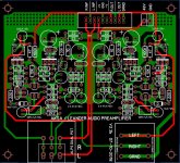
I don´t personally like signal traces who see each other (green/red layers).
Using this parts allows to put potentiometer directly on entry:
- ACHSKUPPLUNG 2: Shaft coupler from 6mm to 6 mm at reichelt elektronik
- P6 ACHSE: Extension shaft 6 mm at reichelt elektronik
KSA and DN needs heatsinking.
JP
...
I don´t personally like signal traces who see each other (green/red layers)...
JP
I am describing layers on a bog standard 2 layer PCB. I don't understand what you mean by 'seeing each other'. Could you please elaborate??
...
... KSA and DN needs heatsinking.
JP
Yea, in this first pass I have done little beyond adapt an existing layout.
The PCB as shown is intended to be attached to the front panel. No pot extensions are required. The ribbon cable to the IO board allows for depth differences in enclosures.
Avoid, as possible, crossing red layer and green layer routed signals.
Well, yes, I‘m coming from HF development.
JP
Well, yes, I‘m coming from HF development.
JP
Avoid, as possible, crossing red layer and green layer routed signals.
Well, yes, I‘m coming from HF development.
JP
Aah, Okay. Please note that 90+ percent of the topside 'red' signal traces are positioned above ground on the bottom side of the PCB.
Thanks for the help with the copper heat sinks. I have some chip amps and a few others to hone my copper skills on before building discretes. I am going to save some copper for the Alpha's to maybe beef up the heat sinks on the cpu coolers. Love to experiment!!!
Cheers
McD
Cheers
McD
Hi X What is it your suggestion for a 3,3k load and an amp with 15dB gain?
Have you figured it out? It would be awesome if somebody explained the math behind this, or pointed in the direction of a post/video doing so.
The gain is controlled by R10 and R11 through the relationship:
G = (R10+R11)/R11
If we set R10 as 10k and R11 as 2k2, we get G=5.55x
Gain in dB = 20 log10(Vout/Vin) = 20 log10(5.55x) = 14.8dB
A load of 3k3 is not hard for this preamp to drive. maybe increase bias current a bit by lowering R15 to 39R, and maybe R14 to 8R2 (or leave at 10R). R15 is the critical controller of the bias setpoint. Make sure the bias does not exceed 75% of the max for KSA1381 (Q4).
Last edited:
Thanks X!
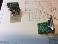
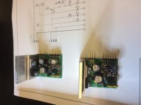
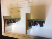
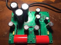
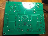
I started populating the board yesterday. It's my first soldering job so I wanted to show here and please let me know if anything is too bad!
I am still missing a few things on the MB but soldered all I had.
A few questions:
1- Mouser didn't have the SMD 2W R161. Is it OK to put TH there?
2- My delivery was missing C121 and C131 (220pF 100V). I will complain, but I have a couple 220uF 100V I bought too many, would that be too large?
3- I forgot to order R141 and R142. Will 0.5W resistors work in these positions? If not I can get them locally.
4- L161 I got at mouser is way too big (15A version) and didn't fit. I will get a smaller one locally.
5- Mouser also delivered the molex 90 degrees wrong. I got 3 pin connectors instead of 10 pins connectors, so I don't have enough.. 🙁
6- My bad on C134. I forgot it doesn't fit there. Will need to relocate so the DB fits.....
Attachments
Last edited:
- Home
- Source & Line
- Analog Line Level
- AKSA's Lender Preamp with 40Vpp Output