C143
I'm having issues to source a 1uF poly cap (MKS recommended) for C143 (lead pitch 7.5mm) - can an electrolytic be used here?
I'm having issues to source a 1uF poly cap (MKS recommended) for C143 (lead pitch 7.5mm) - can an electrolytic be used here?
That’s the cap Mx snubber. Use a ceramic x7r is ok and other materials like mkt FKP etc bit not electrolytic. Value can be larger 2.2u etc.
Thanks X - X7R is easy to get and will fit in the 7.5mm space. I actually found a 1uF poly cap in my parts bin from a previous Cap Mx project that will fit here!


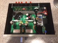

That looks awesome JPS, very professional fit and finish. Do you plan on GB for the Heat sinks at all? I have standard type eBay ones coming but those are next level
JP,
I looked at your drawings for your aluminum heat sinks. I have some 6.2mm x 50.8mm copper bars (178mm long) that I can use for heat sinks. Is it recommended to use copper rather than aluminum.
Also, been a long time since I looked at this thread, was wondering which transistor's the heat sink's are designed for.
Thanks for the help,
McD
Looks great JP! Nice and compact chassis.
I would definitely be in for a GB of those heatsinks for mine.
I would definitely be in for a GB of those heatsinks for mine.
JP,
I looked at your drawings for your aluminum heat sinks. I have some 6.2mm x 50.8mm copper bars (178mm long) that I can use for heat sinks. Is it recommended to use copper rather than aluminum.
Also, been a long time since I looked at this thread, was wondering which transistor's the heat sink's are designed for.
Thanks for the help,
McD
Jumping in here. Aluminum is a bit better than copper but negligible difference.
I think JP is going still to have this design proven. I hope it works but personally I’m not to confident on a finless design.
Copper is a better heat conductor and is used on some CPU coolers as the active contact patch. However it is very difficult to drill and tap by hand. Aluminum is not as high but infinitely easier to drill and tap and a lot less expensive.
Finless can work if the bulk volume and surface area permit sufficient heat transfer. These transistors in HPA mode are dropping 12v ea x 100ma or 1.2w ea or about 2.5w per channel. You don’t need a huge heatsink for that. In preamp mode they are 24v ea x 35mA or 0.84w ea and 1.6w per channel.
Finless can work if the bulk volume and surface area permit sufficient heat transfer. These transistors in HPA mode are dropping 12v ea x 100ma or 1.2w ea or about 2.5w per channel. You don’t need a huge heatsink for that. In preamp mode they are 24v ea x 35mA or 0.84w ea and 1.6w per channel.
Copper is a better heat conductor and is used on some CPU coolers as the active contact patch. However it is very difficult to drill and tap by hand. Aluminum is not as high but infinitely easier to drill and tap and a lot less expensive.
Finless can work if the bulk volume and surface area permit sufficient heat transfer. These transistors in HPA mode are dropping 12v ea x 100ma or 1.2w ea or about 2.5w per channel. You don’t need a huge heatsink for that. In preamp mode they are 24v ea x 35mA or 0.84w ea and 1.6w per channel.
Yes sorry. I had it switched... copper is better.
I didn’t know the dissipation was only 2.5W. Much more confident that way
JP,
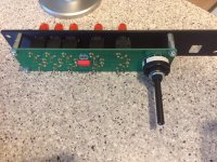
I see that the on-board RCA connectors for the selector PCB have been populated. I might be wrong, but IIRC there was some difficulty sourcing this earlier? May we know the model number and source?
And your build is looking compact and functional. 🙂
I see that the on-board RCA connectors for the selector PCB have been populated. I might be wrong, but IIRC there was some difficulty sourcing this earlier? May we know the model number and source?
And your build is looking compact and functional. 🙂
I found them when I was buying my stuff, but they were costly... I ended up buying panel mount RCAs and will wire directly to the board (I'm bypassing the selector, but if had a selector would then wire to the selector board).
Yesterday I found this article on heatsinks that seems interesting:
How Much Heat can be Extracted from a Heat Sink? | Electronics Cooling
Yesterday I found this article on heatsinks that seems interesting:
How Much Heat can be Extracted from a Heat Sink? | Electronics Cooling
- Home
- Source & Line
- Analog Line Level
- AKSA's Lender Preamp with 40Vpp Output